Wendell Folks RV-8 Project - Page 17.
April 11, 2006: After getting back from
Sun-N-Fun, Wendell was ready to get back to work on the airplane. During Monday and
Tuesday evening work sessions, we rolled the fuselage over and leveled the front area as
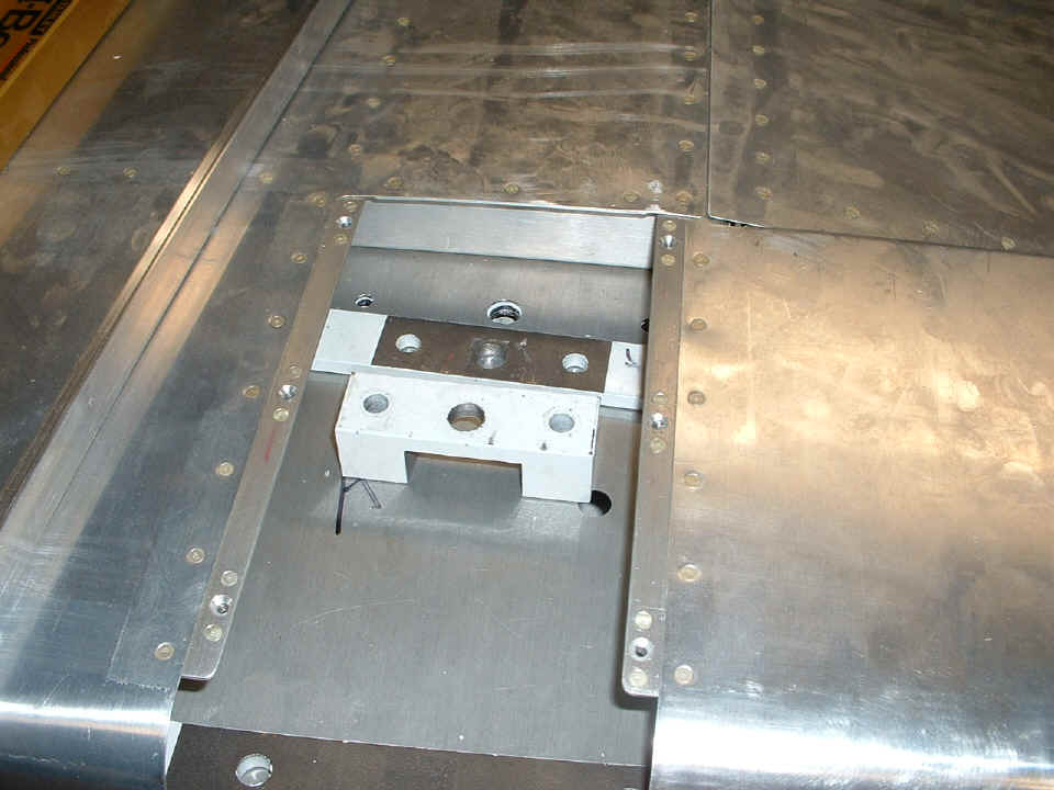
needed to fit the landing gear legs. That also required the drilling of the mounting
blocks on the drill press. Here are two of those blocks and the matching 7/16"
hole and two 1/4" holes that were drilled through the steel component already
installed inside the quickbuild fuselage.
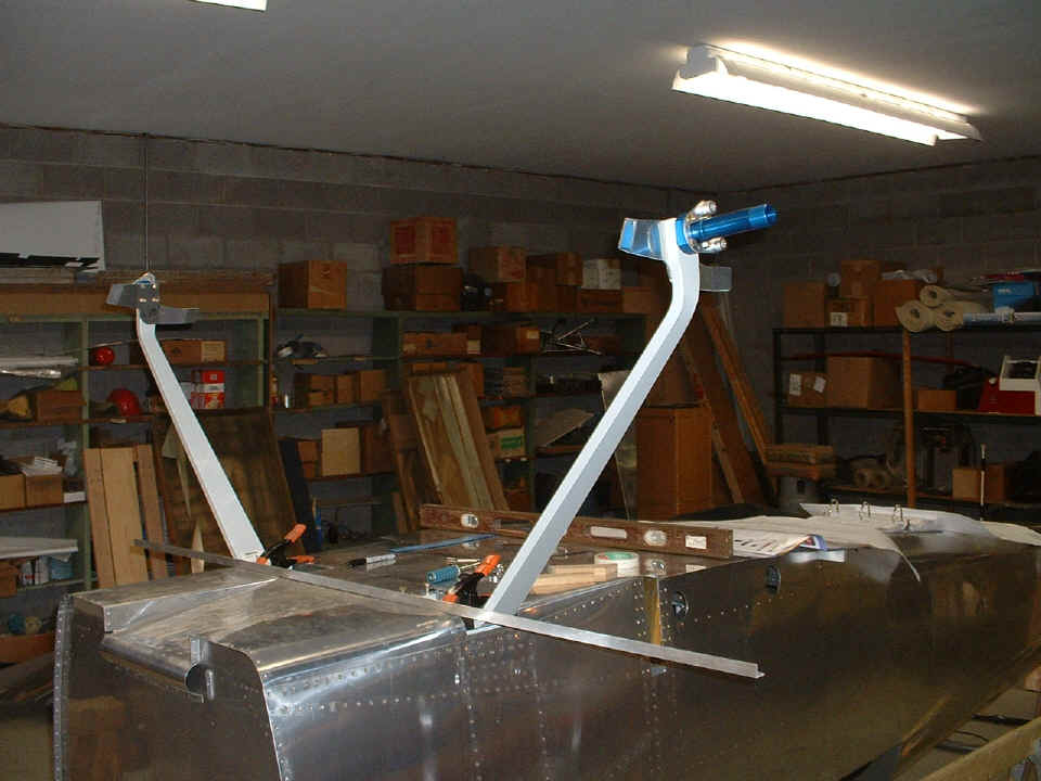
Here is the first fit of the gear legs on the fuselage just before we called it
a night. The critical alignment of the legs will be in the next session. That
piece of aluminum angle will be aligned with the rivets in the bulkhead just forward of
the gear leg towers inside the fuselage. The forward edge of the gear legs and the
blue axles themselves should match up parallel with the aluminum angle according to the
plans and instructions. At least we have been able to find all the pieces and put
them together for this photo.
Wendell and his airport partner Jim have been improving the south end of the air strip. We met with the earth moving guys and walked that part of the strip that is being finished in the coming days and weeks. He called me tonight before I posted this page to tell me that additional truck loads of dirt have already been brought in to provide a smoother surface for that end of the runway.
April 16, 2006: It is Sunday morning and time to update the web with recent activities on Wendell's project. I spent Saturday afternoon working with Wendell to align the landing gear legs with the centerline of the fuselage. After getting the proper alignment using two methods that affirmed each other, the critical bolt holes were drilled into the lower longerons and the steel weldments of the gear leg towers inside the fuselage. A rivet on the fuselage centerline near the tail was used as a reference point to the outer end of each blue axle. The final measurement was 165 inches from the center of that rivet to the end of each axle. At the same time, a string stretched across 3/4" blocks attached to the axles confirmed the axles were parallel to each other to insure the main wheels would not have any toe-out or toe-in conditions to cause excessive tire wear. After helping Wendell get this process right, I was so glad that my RV-9A was designed differently with all this alignment problem avoided.
Before the final alignment could be accomplished, some of the fuselage skin had
to be removed to clear the steel gear attachment blocks.
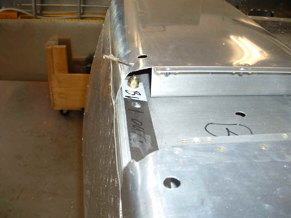
As is the case too often, I get too involved with the process to take any
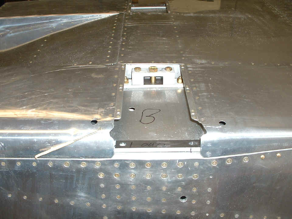
pictures during the critical steps. The photo below shows the inner attach blocks
and the five bolts that secure the components. The large bolt is the main pivot bolt
that holds the end of the gear leg to one of the steel weldments inside the fuselage.
The two bolts on each side of it also secure the cold-rolled steel block that
provides additional strength to the gear leg attachment. The two 1/4" bolts
with the nuts showing at the edges of the gear cover opening are there to hold the steel
wear block to the fuselage. At the near end of the opening, the outer steel wear
block is visible, but the 1/4" bolts and nuts holding it in place are below the holes
that are drilled in the skin on each side of the gear leg cover opening. All of that
ragged area and the those two holes in the skin will be covered by the fiberglass gear leg
fairings.
This photo shows one of the bolts and nuts that hold the outer gear leg wear
block to the lower longeron. Again, this 1/4" bolt secures only the wear block
between the fuselage and the steel landing gear leg. Due to the close position of
the gear leg tower inside the fuselage, the 1/4" holes at the ends of these wear
blocks were used to back-drill into the lower longerons via the hole in the skin above
those 1/4" bolts and nuts. Two 3/8" bolts go through the cold-rolled steel
blocks to secure the gear leg to the steel weldment and the lower longeron inside the
fuselage. Those two 3/8" holes were the ones that required the precision
alignment of the gear legs before they could be drilled.
At the end of this session, the gear legs were put up on the work table to have the axles disassembled and stored away until it is time to put all this back together before mounting the engine. For now, it is time to clean off the oily residue from the belly that was used for the quick-build shipping process from overseas. The next session will see the fuselage turned upright again in preparation for the attachment of the horizontal and vertical stabilizers. Then the fun begins with the installation of the elevator trim cable, pitot static air lines, instruments, more wiring, etc. The week ahead is when Wendell orders his engine, the flight instruments, radios, etc. More later...
April 23, 2006: It is Sunday again and time to post the latest news from Wendell's shop. Saturday afternoon saw Wendell and I getting together late in the day and working until past 9 PM. The focus today was on getting the horizontal stabilizer aligned and match-drilled to the aft deck of the fuselage. Before anything could be done, the fuselage was leveled both horizontally and longitudinally. I also showed Wendell how to verify that the fuselage had no twist to it by checking the horizontal leveling of the aft deck. Any error here can easily be overcome with a thin metal shim as needed to also level the horizontal stabilizer so that it will come out parallel with the main wing when it is installed later.
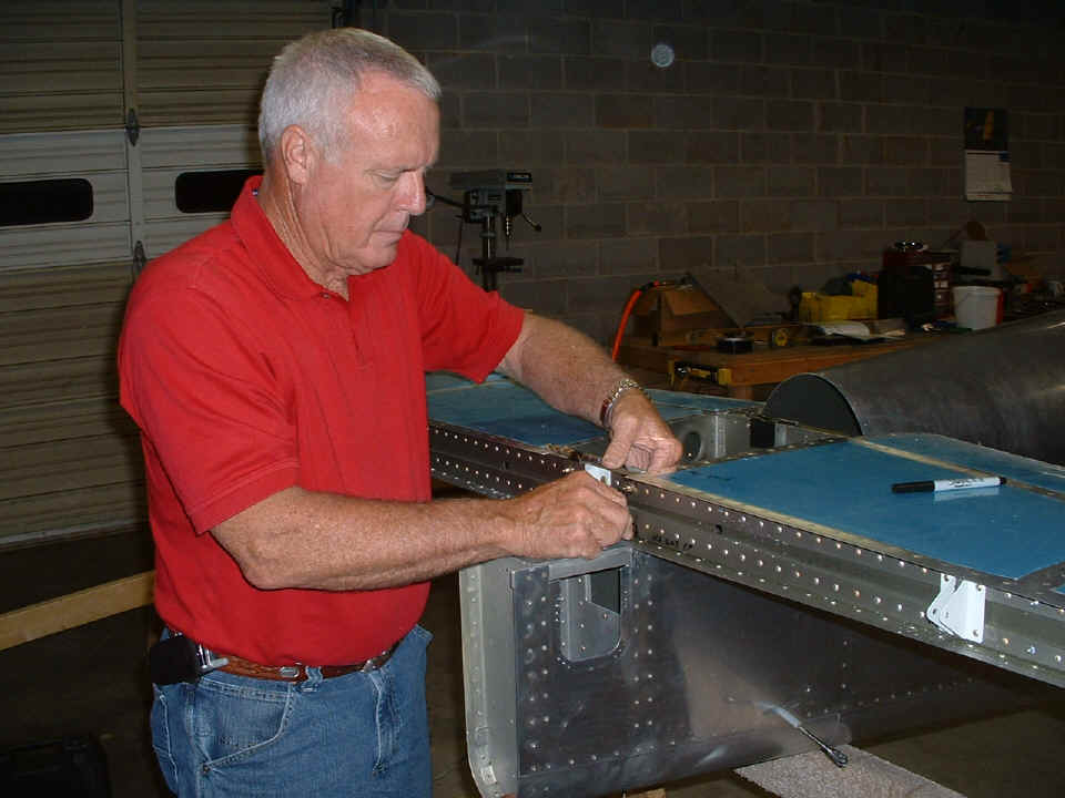
As always, when I am working with Wendell on critical measurements, there are
no pictures until the precision work is completed. In this case, the measurement to
the center rivet on the fuselage above the back seat was confirmed to both aft corners of
the horizontal stabilizer. The magic number for Wendell's RV-8 was 104 and 9/16
inches. A long #30 drill bit was used to access the lower flange of the horizontal
stabilizer front spar. Clecoes were installed and the alignment of the HS was
checked after each hole was drilled. When all EIGHT holes were drilled and the
alignment was confirmed one last time, all the #30 holes were enlarged to accept the AN-3
bolts that will hold the stabilizer to the fuselage. Wendell installs a few bolts
after all the precision alignment and drilling is completed.
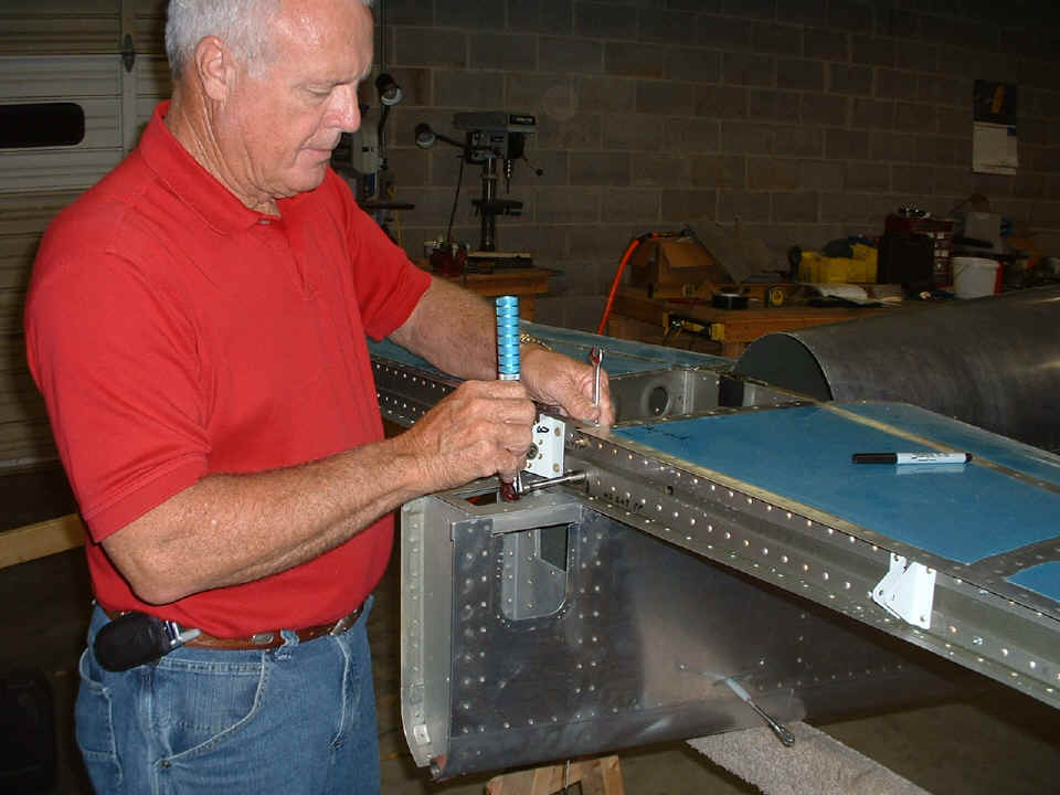
The horizontal stabilizer will be removed later, but for now, I make sure he is
familiar with proper torque settings for AN-3 bolts. Two 1/8" spacers had to be
fabricated before the wing incidence of the horizontal stabilizer could be set. What
we did not take time to photograph were the clamps that held the HS rear spar to the two
heavy bars that hold it secure. Per the plans, we used a 1/4" drill bit on the
front spar of the HS, and a 5/16" drill bit on the aft spar. We selected a
suitable-sized drill bit and put it under the aft spar to maintain the proper incidence
before clamping and drilling the aft spar to the heavy bars that are part of the fuselage.
My short level sat on the two drill bits during this alignment process.
Looking at the forward spar of the horizontal stabilizer, you can see the black duct tape
holding the 1/4" drill bit to the top center of the spar. We had the level on
it and the 5/16" drill bit that was taped to the aft spar of the horizontal
stabilizer.
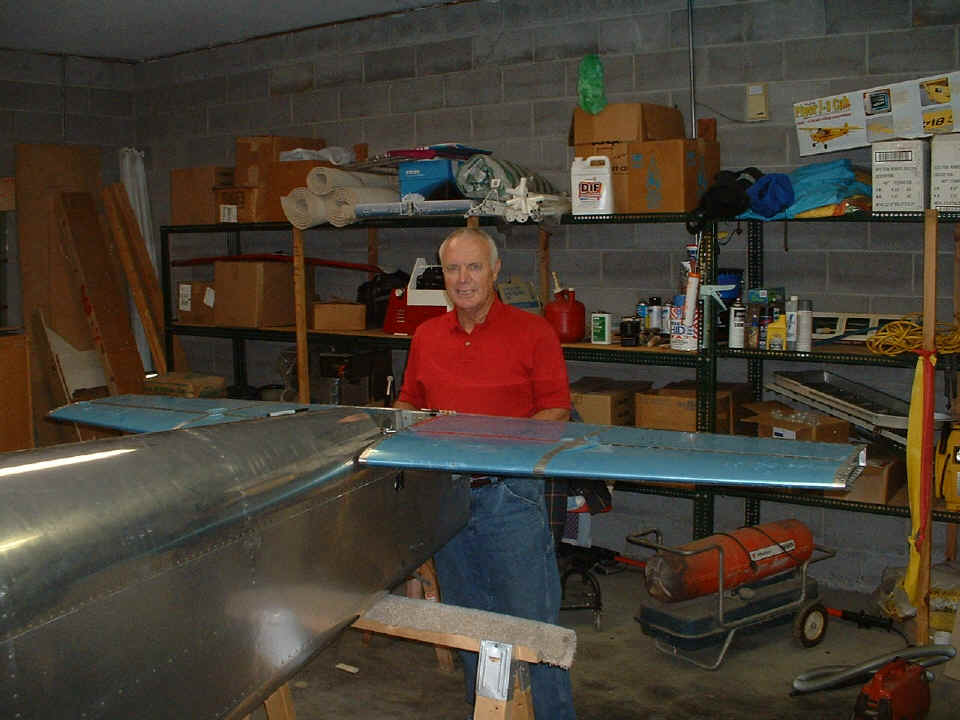
A good portion of the evening was spent studying the blue prints before the
completion of match-drilling of the spars of the horizontal stabilizer. This was
another one of those "milestone" days. The next work session will see the
installation of the vertical stabilizer.
The problems with the design of the RV-8 horizontal stabilizer become evident when one tries to install the nuts on the four bolts holding the front spar of the HS to the aft deck and longerons. You either need to have a thin person with long arms inside the fuselage to put the nuts and washers on those bolts, or you cut an access plate in the side of the fuselage just below and in front of the horizontal stabilizer. John Myers used the access port idea to install his bolts, washers, and nuts on his HS forward spar. Stay tuned as we discover how we are going to get those nuts in place and secured. The RV-7 and RV-9 were designed after the RV-8 and have easier access to install the four bolts at the front of the horizontal stabilizer front spar. I did not have to face this problem with my airplane.
| CLICK for Folks PAGE 18 | Return to Other RV Menu | Return to Main Menu Page. |