INSTRUMENT PANEL - Page 75.
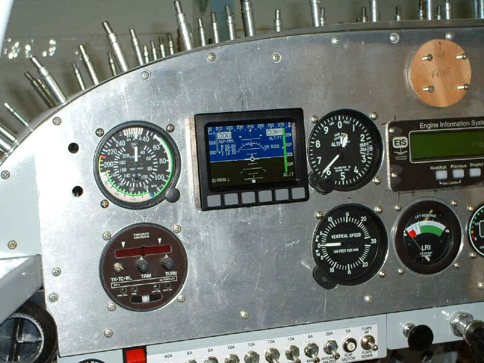
December 13, 2004: The Dynon D-10A has
arrived as expected. I have already tested it, updated the software that was
released while it was enroute to me, and placed it into the instrument panel. It has
the optional internal backup battery and it is shown below operating on that battery.
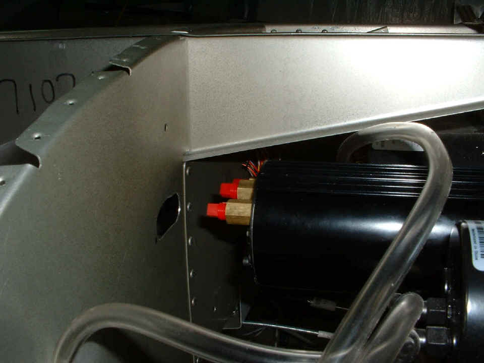
I took the cowl off and the upper forward fuselage skin to get access to the
area behind the panel. I wanted to see where I would have to cut access holes for
the Dynon serial cables, power wires, and the cable that runs to the remote compass sensor
and outside air temperature (OAT) sensor. That hole that is in there was done
tonight with my large unibit in two locations, then connected using the hand nibbling
tool. When I had the cables routed through it, I decided it was not large enough.
I have right angle connectors for the air lines to keep them from going through
that bulkhead. I will enlarge the hole in a later session.
I have to finish what I am doing up front on engine baffles and air seal fabric, then my attention moves to the instrument panel and wiring again. Stay tuned, there is more to come! The construction log book time now stands at 1412.9 hours of aircraft construction.
December 14, 2004: What can I say, the
engine baffles and air seal fabric are in a holding pattern. I got to work on the
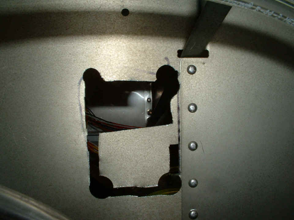
area behind the Dynon unit to clear the cables and air lines from the pitot/static ports.
Here is the work in progress of drilling and hand nibbling. I put the digital
camera in "macro" mode and shot this through the front panel mounting hole for
the Dynon unit. I will give you a shot of the finished hole in a later session.
I finished it tonight, but forgot to take a picture of it.
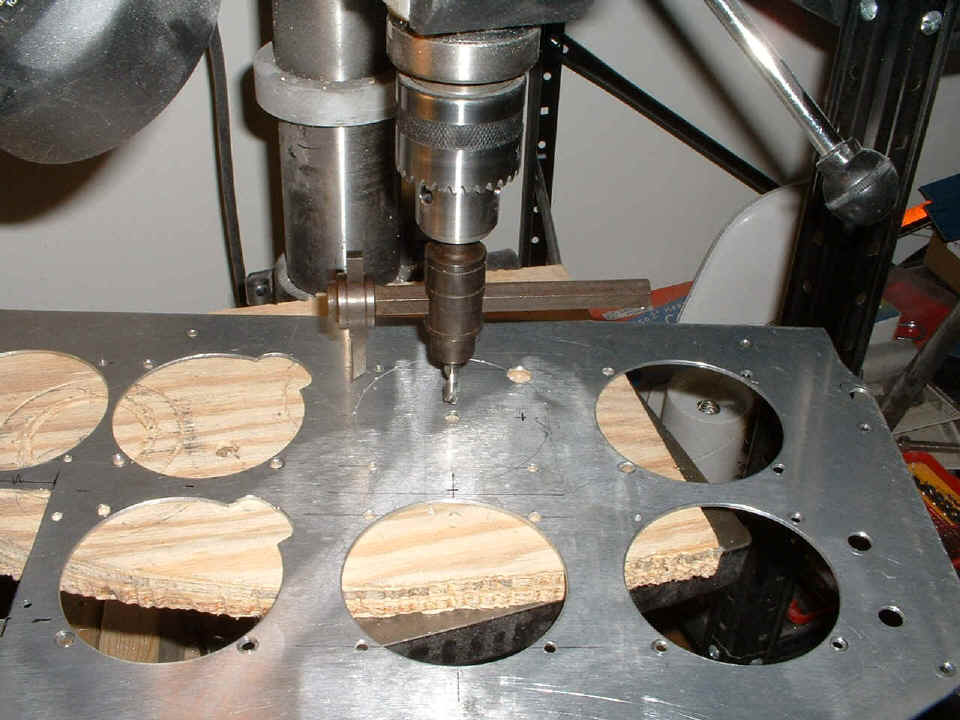
This second shot of the day shows how I did the hole layout for the NAV
receiver VOR/ILS
CDI display unit. It will be driven by the NAV portion of the Garmin
SL-30 NAV/COM receiver that will be installed in the radio stack.
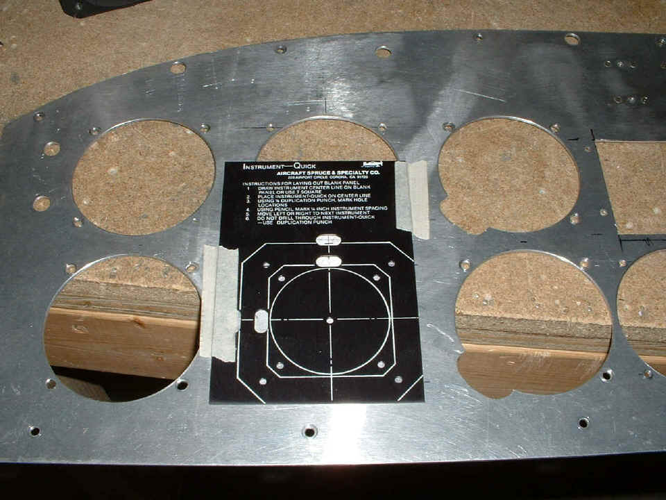
After doing that layout, there is of course the work on the drill press to put
the holes where they need to go. You can see where I have drilled the three mounting
screw holes around the edges of the instrument opening. The larger fourth hole is
for clearance of the OBS selector knob. You can see that I have very lightly scribed
the surface to confirm that the hole cutter is properly adjusted before making the cut all
the way through.
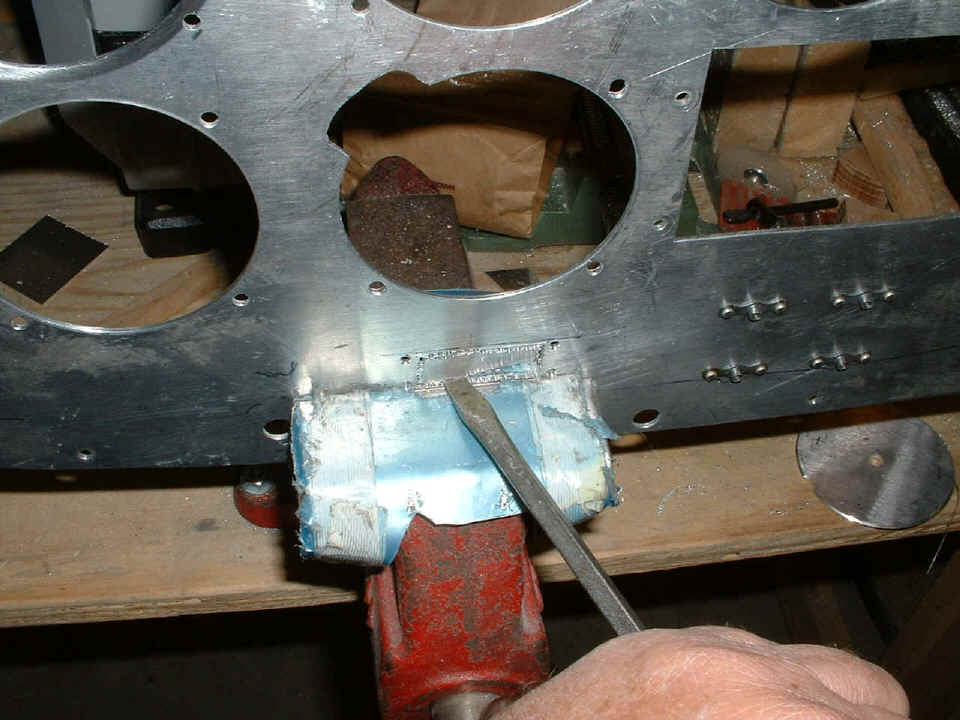
Here you can see that I am preparing a rectangular hole for the ELT control
panel. I had drilled numerous small holes inside the scribe lines that will allow
the passage of the body of the miniature control panel through the aluminum plate.
Look carefully and you will see the four mounting screw holes near the corners of the
rectangle. This photo is looking from the back side of the panel. The four
platenuts near the right side of the photo hold the GPS mounting bracket.
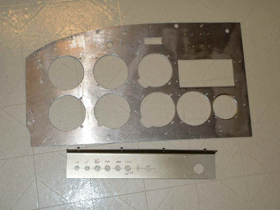
And the last shot of the night is the finished product of tonight's work on the
kitchen floor. The new little rectangular hole is finished with precision filing and
two new small round holes for warning and indicator lights are above the Dynon mounting
location. I have to get one more warning light to install there before I prepare the
plate for painting. The other electrical sub-panel has a few new holes in it also.
I mounted the panel light dimmer circuit board behind the four very small holes you
see. There is a 1/4" hole for mounting the dimmer control potentiometer (POT),
and a new switch hole just to the right of it. The circuit
breakers for this panel are first shown back on page 59.
| CLICK HERE for Instrument Panel page 76. | RETURN to MAIN MENU |