
INSTRUMENT PANEL - Page 76.
December 15, 2004: I went out shopping for a few items this evening. I picked up another SPDT switch for essential power bus control to selected avionics and the solid state ignition module. I also got some sockets for D-sub connectors and a crimper for them to connect the wires from the OAT sensor to the Dynon remote compass module when the time comes. I put two of the connectors on the appropriate wires to try my hand at it. All went well!
I had also removed the switch breakers from the main switch panel to remove and
replace the label sheet. Here is the label sheet I created for the switch panel on
the left. The change I made was moving the names to the top side of the
switch/breakers and moving the ampere ratings below. There was no change to the
FLAPS UP / FLAPS DOWN switch. This label is not as wide as the other one since the
MAG/starter key switch came with its own keyed metal label. Each of the labels is
spaced 7/8" on centers to match the spacing of the switch/breakers. January 6, 2005: I made a change to
both labels when I realized I needed to have the Light Speed ignition breaker on the LEFT
panel due to the use of shielded wire from the battery to the breaker to the LSE module
under the panel. The MAP LIGHTS switched circuit
breaker moved to the RIGHT panel shown further down the page.
And the label for the switches and breakers on the right side is below. I
moved a couple of them around. The first two on the left are pullable breakers.
Next comes a SPDT switch to allow me to put the "essential bus" directly
to the battery or put it on the "MASTER". That switch has a center OFF
position. The next three are regular circuit breakers for the Garmin radar
transponder, the field current to the alternator (which goes through the RED Cessna
ALT/Master switch next to the MAG/starter key switch on the other panel above. The
AUX CIRCUITS will power the sound system (tape player/CD combo) for any bored passengers
on long cross country trips. The light dimmer works only on lights that shine on the
instrument panel. CABIN LIGHTS is another SPDT switch that will operate strings of
white LED lights that I have acquired.

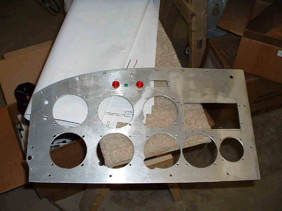
I finished up the last hole in the instrument panel for the second RED warning
light. It turns out that the light that came with my Grand Rapids Technology engine
information system (EIS) is exactly like the two that I bought at Radio Shack tonight.
They are 12-volt RED LED lights that draw 100 mA each. These two lights will
almost never be lit (I hope!). The one over the center of the Dynon location will be
tied to the oil pressure switch that also drives the Hobbs hour meter. When the oil
pressure is low and the master switch is ON, the light goes ON. With normal oil
pressure, the light is OFF and the Hobbs meter runs. The GREEN LED light will be
attached to the essential bus or possibly the "keep alive" input voltage to the
Dynon unit -- I haven't decided which yet. The RED LED next to the ELT panel
rectangular opening is ALARM fault from the GRT EIS engine monitor. It can be
programmed to go off for any parameter that is out of normal range. If you wonder
why these three lights are spaced unevenly, look at the larger screw hole above and
slightly right of the green LED. That is where one of the ribs is located behind the
panel.
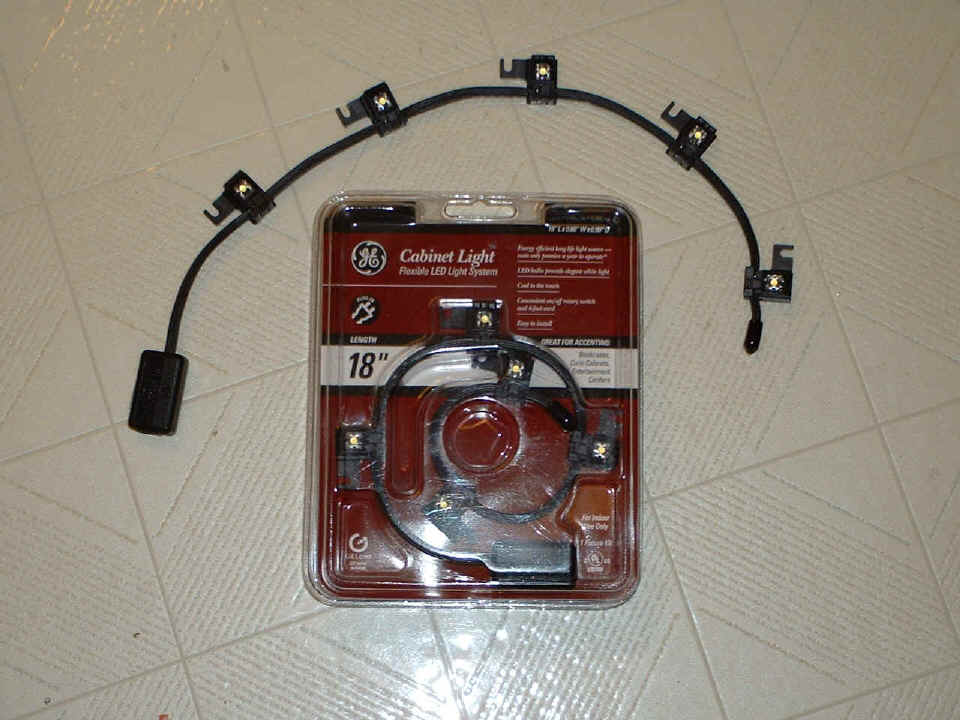
The last photo of the night shows a package of "Cabinet Lights" I found at Wal-Mart of all places for $14. This string of WHITE LED's is wired parallel on a 4.5-volt DC bus. It is pretty obvious that they could be wired in series in groups of three and connected directly to the 12-volt bus. I measured the charge on my Odyssey battery tonight at 13 volts DC. If you decide to do that, be sure to observe the correct polarity of each LED as you connect them in series. Each LED light can be attached with screws or double-sided sticky pads (pads provided in the package).
The package includes a "wall wart" AC to DC power supply to produce
the 4.5 volts DC. The current drain of all five LED's is only 330 mA, or 65 mA for
each LED. I will be placing two of these strips in the overhead area of the baggage
area. I am also toying with the idea of placing another strip under the glare shield
over the instrument panel and connecting them to the 12-volt light dimmer bus through a
voltage-dropping resistor. Why you ask about the dropping resistor if I have a
dimmer circuit? Because there will also be two "eyeball lights" on that
light dimmer circuit that are 12-volt rated incandescent bulbs. Or I could just
rewire them to become TWO groups of three LED's in series WITHOUT the resistor. I
bought FOUR packages of these WHITE LED's.
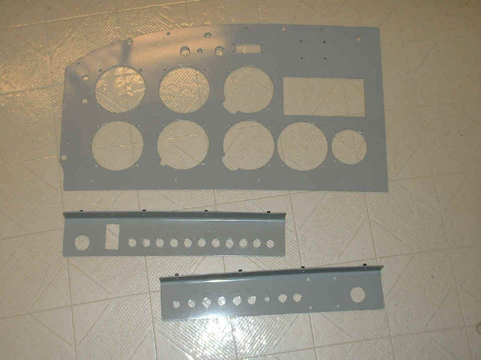
December 17, 2004: I took one day off from
the airplane but managed to get going again today with a short spray paint session on the
driveway late in the afternoon. Here is the result of the first coat of paint on the
main instrument panel. I put a second coat on the main switch/breaker panel, and the
first coat on the switch/breaker panel for the right side of the airplane. I have to
buff the main panel before putting the second coat on it tomorrow, weather permitting
that
is, if it remains sunny outside.
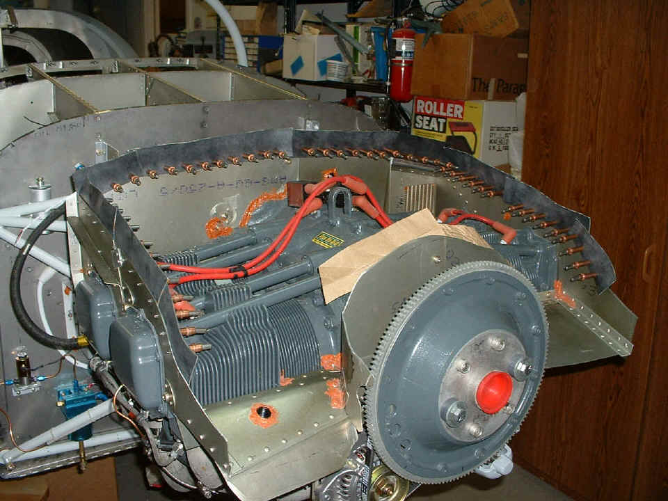
In my work session after dinner, I cut out some paper templates to represent
the air seal fabric on the engine baffles. I put the upper cowl on right after I
took this picture and it is looking good under there.
The other item to note today is the remaining avionics order being placed with Van's Aircraft for the Garmin SL-30 COMM/NAV receiver, Garmin GI-106A VOR/LOC/GS/CDI, and the Garmin GMA-340 audio panel with built-in marker beacon receiver. That order was signed and faxed to Van's today. They allowed online ordering of the antennas, so the AV-532L VOR/GS antenna with balun and cable will connect to the NAV receive side of the SL-30. The AV-10 COMM antenna will connect to the communications transceiver port of the SL-30. And the last one is the 75 MHz antenna to feed the marker beacon receiver in the GMA-340 audio panel. That panel also supports two external personal stereo audio sources.
Add another three hours to the construction log book for this date. That brings the construction time to 1423.9 hours.
December 18, 2004: Saturdays can be
productive and today was moderately so. I got the second coat of paint on the
instrument panel and the right switch panel early in the day. The weather was good,
so there was not a problem painting the few pieces that needed to be done. After
getting the paint on and setting the pieces aside to dry, I started changing out the paper
templates for real pieces of air seal fabric. I still have to finish the air seal
fabric near the front on both sides and across the top behind the ring gear as seen below.
Each piece is 2" wide and varies in length as needed. I put a mark at
the 5/8" width and overlapped that much with the aluminum baffles. That left
1.375" of fabric to close the gaps between the baffles and the inside of the
upper cowl. While I had the lower cowl off the fuselage, I took off one platenut on
each side of the spinner that was too close to the ring gear. There are still two
platenuts on each side to provide screw attach points joining the upper and lower cowl
sections together near the ring gear.
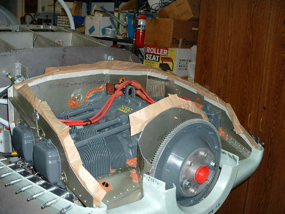
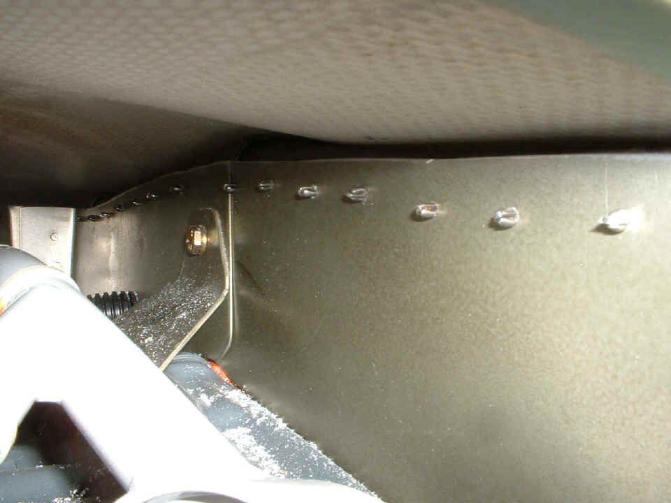
Since I could not get to a good vantage point to see the amount of clearance
when the cowl was put back on the fuselage. I put the camera in macro mode and
shoved it inside the oil access door to see the amount of clearance at the center back
side of the baffles. And here is how that looks inside the cowl at the back.
Just to give you some perspective, that blue gray color metal in in the center with the
dust on it is the upper back side of the engine crank case. That black corrugated
tube is the blast tube to provide cooling air to the magneto. And of course, those
metal tips sticking through the primed aluminum plate are the front end of 1/8"
clecoes holding the air seal fabric to the baffles for now.
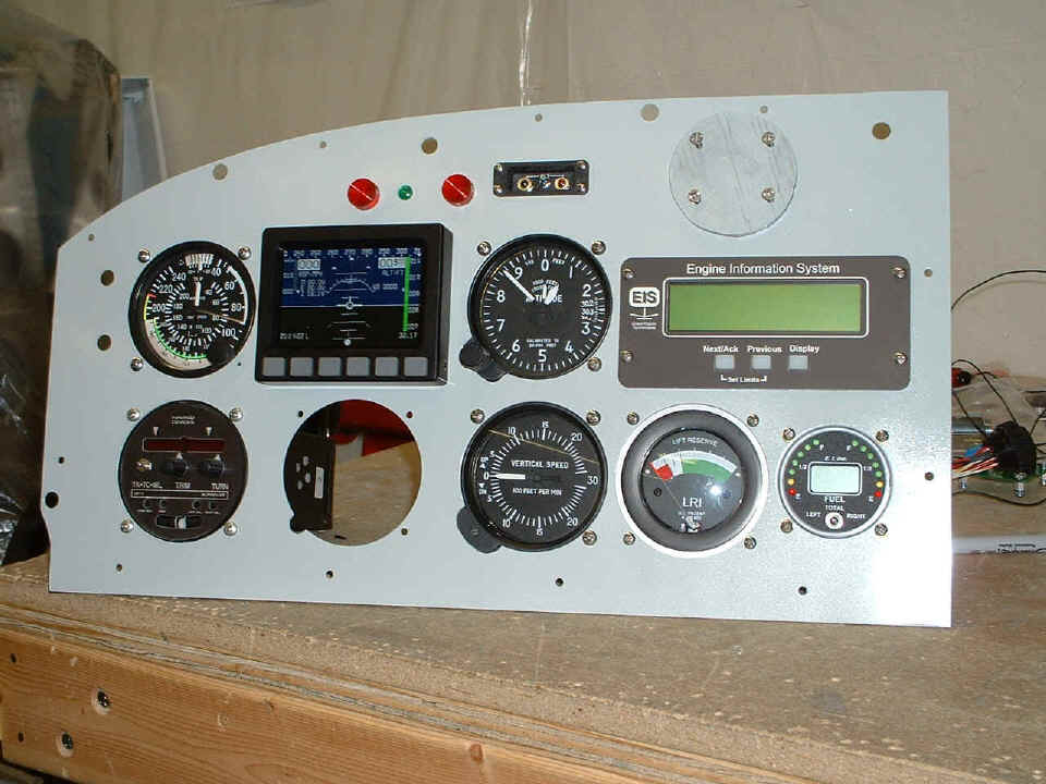
After the paint dried most of the day, I put all the instruments into the panel
for what should be the "last time". This includes the Dynon D-10A, which
was bolted in for the first time. I also interconnected the pitot and static air
lines to the instruments. I just realized there is a reflection across the vertical
speed indicator and the lift reserve indicator. The instruments are clean. I
turned on the Dynon using the internal standby battery for this photo. Not long
after this was taken, I put the panel back in the cockpit and secured it with two screws
to keep it out of the way and protected. That last instrument hole below the Dynon
unit should be filled some time in January. And yes, you can see I painted the
plywood disc spacer that goes behind the GPS mounting bracket, which is not shown on the
panel at this time.
Not a bad week if I say so myself! Today's mail brought my copy of the aircraft registration from the FAA. The avionics and antennas were ordered yesterday. I got a good lead on hangar space when the week started. Today I called my local EAA advisor to have him drop by to look over my work and point me in the right direction on wire routing and chaffing issues. He also told me that a hangar could be available soon at Collegedale Airport also.
December 19, 2004: I spent some time with my youngest son today to take in a movie and do some Christmas Shopping. He got a new TV, I got lunch. I got home and put in 2.9 hours after dinner tonight working on the air seal fabric on the front baffles. I took off the ring gear and alternator belt in order to get more access to that area and confirm which way the fabric is laying against the upper cowl. I tried more of that close-up camera work under the cowl, but all I got was excessive flash bounce back into the lens.
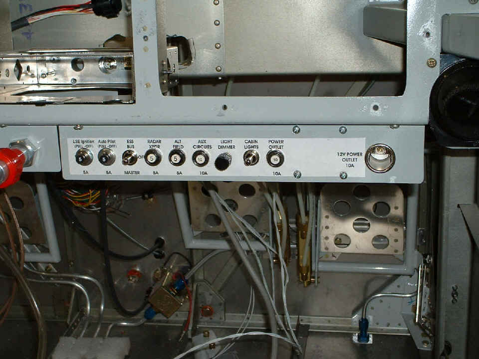
Just one photo for tonight of the switch/breaker panel from the RIGHT side of
the cockpit. I have a mix of breakers and dedicated switches on this side.
From LEFT to RIGHT: Light Speed Ignition pullable 5-amp breaker, Autopilot pullable
5-amp breaker, SPDT switch that will provide power to the essential avionics power bus
from either the MASTER circuit or directly from a fusible link from the battery.
This switch will be in series with the avionics master switch. Next is the radar
transponder (5 amps), ALTERNATOR FIELD (5 amps) which is in series with ALT side of the
RED Cessna MASTER/ALT switch on the other panel. AUX CIRCUITS is a catch all 10-amp
breaker for things like cabin lights, stereo tape/CD player, etc. The LIGHT DIMMER
works on the panel lights only for night illumination of the instrument panel. The
CABIN LIGHTS switch is another of the SPDT switches to turn on lighting above the baggage
area and/or possibly on the roll bar over the seats. That has yet to be
determined. The POWER OUTLET 10-ampere breaker is in series with the cigarette
lighter socket which will be used to power a lap top computer for flight testing or
whatever??? The four screws on that panel secure the circuit board that has the
light dimmer circuit on it for the panel lights.
The total construction time stands at 1432.9 hours. Now that I have both switch panels in place, I feel it is time to get going on wiring some of this stuff and testing some of the electrical items when wired.
| CLICK HERE for Firewall Forward page 77. | RETURN to MAIN MENU |