FIREWALL FORWARD - Page 55.
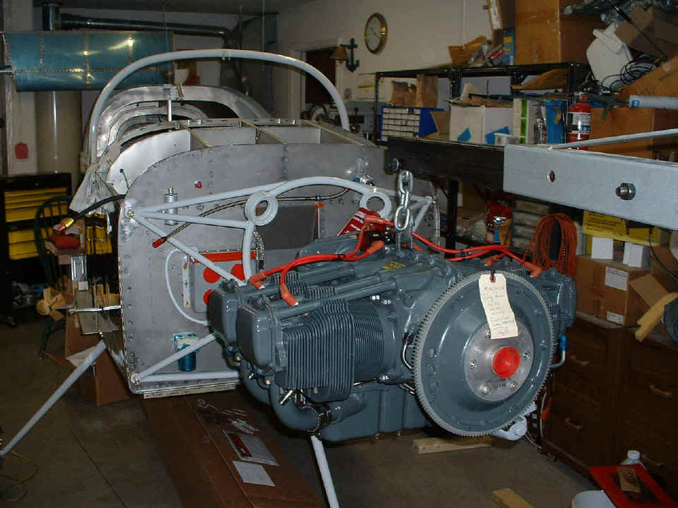
September 11, 2004: Hanging the engine was
the big deal today. I called Rich Nadig after I finished with his hoist and gave him
my old wing jigs to use on RV-4 wings for his Harmon Rocket. Here is my O-320-D1A
hanging from the hoist as I am ready to place it in position for insertion of spacers and
bolts. I removed the spin-on oil filter right after I took this shot to make it easy
to get the engine through the mount. The white tag on the ring gear is a
quality control tag from Penn Yan Aero.
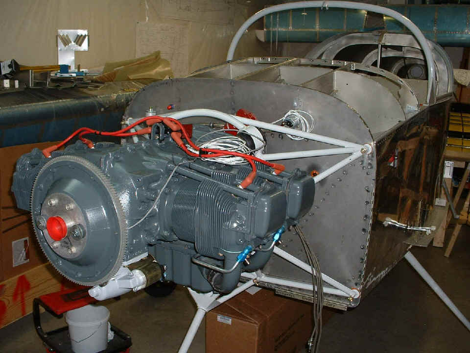
And here it is after putting in all four engine mounting bolts and cotter pins.
Now to start connecting all the stuff that makes it go. You can see all four
of the spark plug wires from the magneto hanging down in the bottom right quadrant of the
picture.
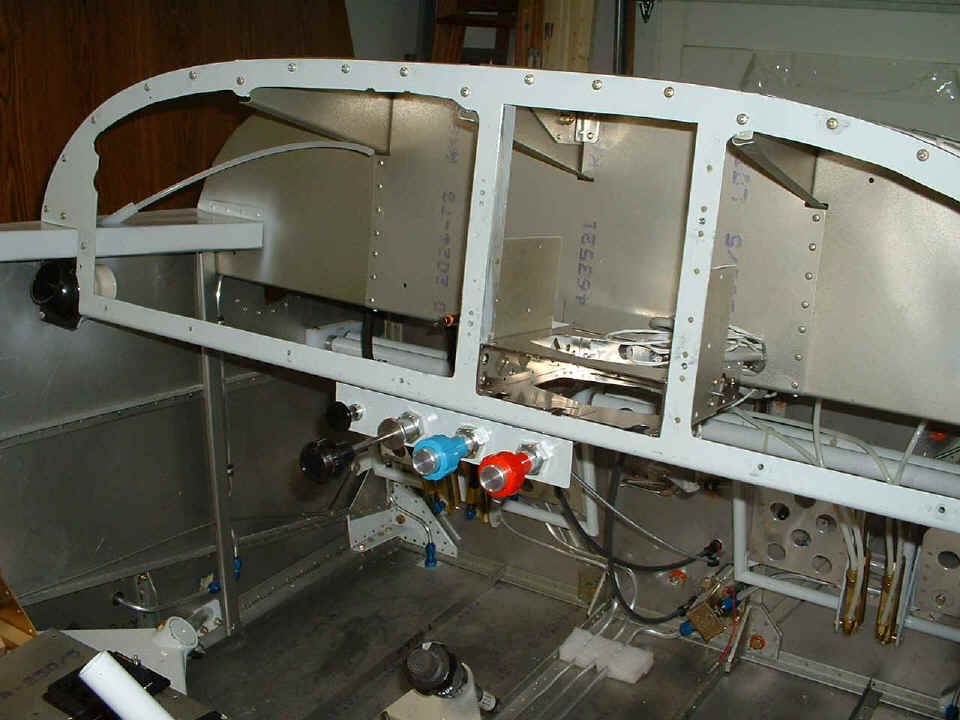
Rather than bore you with photos of the connections to the carburetor for
throttle and mixture, or the propeller control cable to the prop governor, I thought I
would just take this picture of all the controls mounted on the other end of them all.
The only one not connected as of this session is the little black knob on the left
side, which is the carburetor heat control. For some of you who are not pilot savvy,
the other three knobs are throttle (BLACK KNOB), propeller control (BLUE KNOB), and
fuel mixture control (RED KNOB). I still have to install the clamps that keep the cables
inline at the second bulkhead behind the instrument panel. After that, each cable
snakes its way to the firewall where each has a specific point of passage to the engine. I also have to put some more of the RED high-temp RTV silicone into the
fittings that pass each cable through the firewall to seal out vapors, etc.
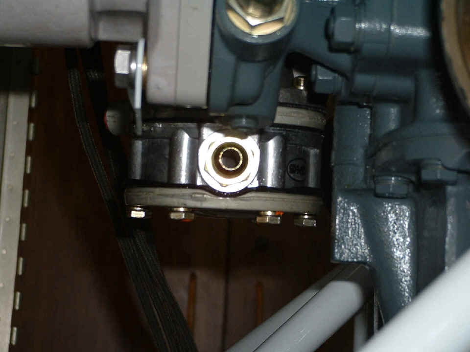
September 12, 2004: I spent part of the day
deciding how to put in the fuel flow sensor for the engine monitor. I realized that
there is a minor issue with getting any hose onto the input of the fuel pump. I
called David Edgemon and he confirmed the same problem with his
RV-9A. Notice how the input fitting on the fuel pump is pointed directly at the
bottom of the adapter for the propeller governor. The large insulated fuel line that
goes there cannot be lined-up to start the threads on the fittings until you take the
bottom of the fuel pump OFF the engine, put the fuel line on, then bolt the bottom of the
fuel pump back together. David reported already doing the same thing on his
airplane.
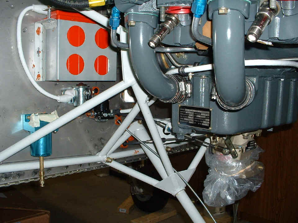
Here you see the results of my installation of the large cable from the starter
solenoid around the oil sump going to the starter. This photo also shows the
BLUE gascolator below and left of the battery. It now has a short brass pipe and
coupler relocating the fuel drain plug to a level below the fuselage and cowling. I
learned this trick from Larry Westbrook in December 2003.
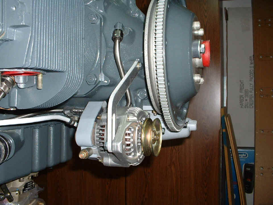
The last shot today shows the alternator now hanging from its assigned
location. That gray item on the far side of the ring gear is the front of the
starter. The stainless steel tube running behind the alternator and up to the side
of the engine is the oil pressure line from the propeller governor going into the
crankcase area to control the pitch of the propeller when it is finally operational.
I have to get a V-belt to turn the alternator and to set its correct position, etc.
Tomorrow I am back on the road for the company for two weeks again. I sent an email to Grand Rapids Technologies to order the other three sensors that I need to activate the additional features.
September 26, 2004 - I am back from the road trip and managed to get a bit of work done today using the parts I bought at Aircraft Spruce & Specialty on the way out of town 13 days ago. I spent a week in Miami, then a week in Washington and a part of Idaho. I flew back to Fort Lauderdale to pick up my car and drove straight home ahead of Hurricane Jeanne. That was a 24-hour day. Up at 6 AM Eastern Time (3 AM PDT) to catch a plane from Spokane to Salt Lake City, then to DFW, and finally to FLL. At least I got a first class seat from SLC to DFW and a meal. I got to my car in long term parking around 6 PM on Friday and drove straight through to East Ridge, Tennessee. I saw quite a few folks checked into hotels when I passed the Valdosta, Georgia area. I bought gas after checking out some hotels and headed for home. I stopped for breakfast around 5 AM to wake up, then finished the last 30 miles.
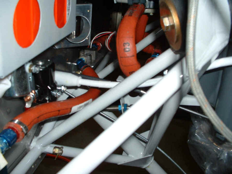
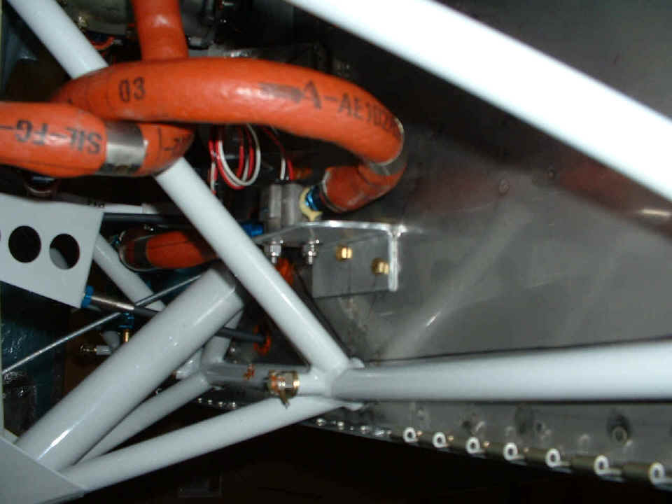
Today was to put the fuel flow sensor in place after fabricating an aluminum angle that I could drill to the firewall stiffeners. I used the extra firesleeve fuel lines I got from David Edgemon to make the connections to the sensor and then to the fuel pump input port. I had to loosen the plate on the bottom of the fuel pump to get the fitting and hose in place. When the plate was put back in place, the firesleeve line pushed up against the bottom of the prop governor. The fuel line going from the gascolator to the input of the fuel flow sensor is at the bottom left of the photo below. The fuel line going to the fuel pump input is the one with the big "03" in the top center of the photo. The gray aluminum body of the fuel flow sensor can be seen with a 45-degree blue AN fitting on it at the end of the hose coming from the gascolator.
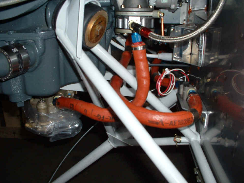
Here is the view from the other side of the fuel flow sensor. The brass
fitting with copper pipe pointing down is the fuel pump overflow tube that has to be
connected to another tube not yet installed. The coil of red, white, and black wires
are coming out the top of the fuel flow sensor. The firesleeve fuel line coming
directly toward the camera doubles back under the fuel pump to make the input connection
shown in the photo above. The silver braided fuel line with the red crimp fitting is
the fuel pressure sensor line going up to the sensor mount on the firewall. The
firesleeve fuel line with the blue AN fitting on it is the one going to the carburetor
input port from the fuel pump.
And here is the last photo for this page and for today, the aluminum angle
bracket fabricated to mount the fuel flow sensor. I drilled out one rivet through
the firewall and replaced it with a 3/16" AN bolt. The other AN bolt is drilled
into the second firewall stiffener half way between two rivets. And yes, there will
be some large tiewraps installed on those fuel lines where they cross each other and
sections of the engine mount - but not now. I seem to find the sharp edges of those
tiewraps when I cut off the ends. My hands and arms have a few scabs and scars to
show for it. I have tried to wipe off my blood stains when that happens. I now
know what "Blood, Sweat, and Tears" really means when building this airplane.
| CLICK HERE for Firewall Forward page 56. | RETURN to MAIN MENU |