FIREWALL FORWARD - Page 56.
September 29, 2004: A short overnight
business trip caused a bit of delay this week, but I got right back to work. I
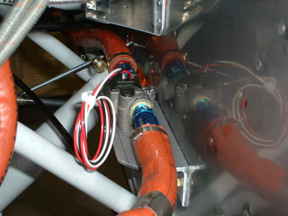
realized while I was away that I had installed the fuel flow sensor with one problem, a
45-degree fitting directly on the input of the sensor. The instructions said to give
it at least FIVE inches of straight or gently bending hose or tubing in front of it.
So I changed it when I got home last night.
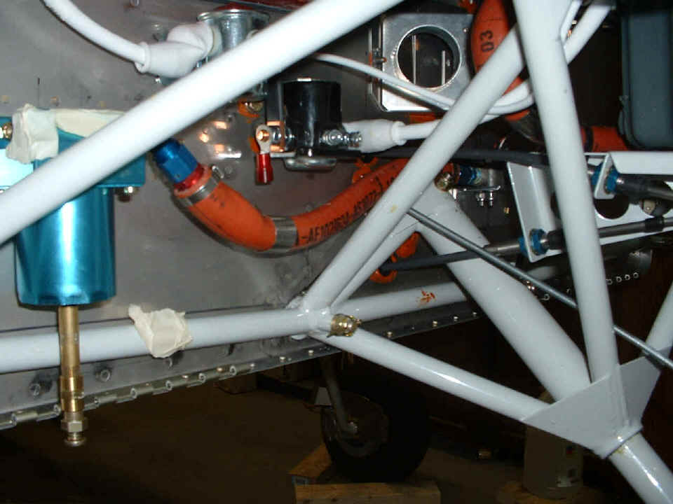
I put the 45-degree pipe-to-tube connector onto the gascolator end of the hose.
It also provided some extra clearance around the starter solenoid.
Today saw the riveting of the F-746 forward engine control bracket to the
F-7105 center bulkhead forward of the instrument panel. All four control cables are
now secured to that new bracket.
I also created a short aluminum angle with a #8 platenut on it and riveted that
to the F-6118 rudder pedal brace. It keeps the propeller control cable from
vibrating around behind the panel.

It is almost time to start putting more stuff in the removable instrument panels. I have ordered a number of switches and circuit breakers and have decided against using fuse blocks for most stuff. It turned out to be a space vs. access issue, and the answer was switches that are also circuit breakers mounted right up front. Keep watching these pages and you will see it all come together, and I will, too!
September 30, 2004: I guess you noticed
above that I was coming from the engine area into the control panel area. Today was
a continuation of that with the cutting of some new holes in the LEFT instrument panel and
mounting the engine monitor, fuel gauge, and the lift reserve indicator.
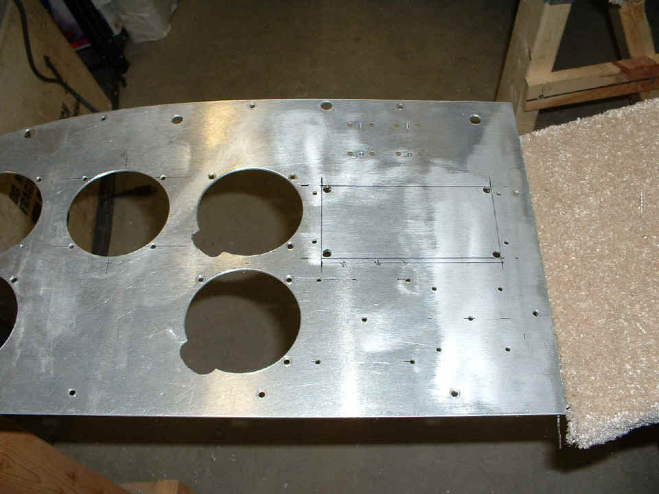
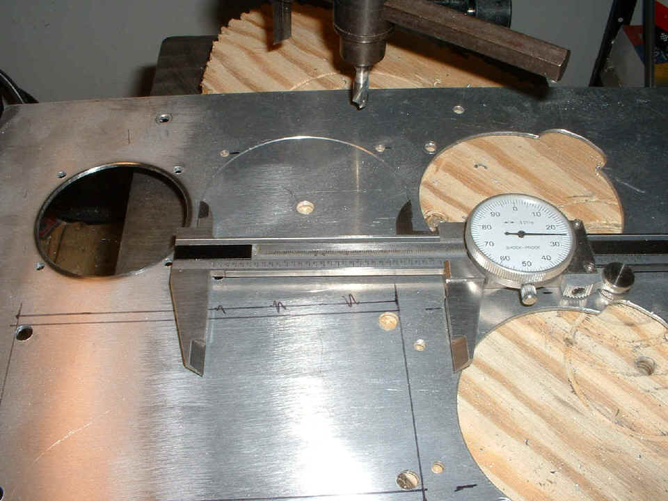
Of course, after drilling the holes, I reviewed the locations and found that I
squeezed a bit in the wrong place. The small hole on the left is for the fuel
gauge.
I scored the panel very lightly and checked the diameter of the second hole for the
lift reserve meter. This hole is FULL SIZED in the event that I may want to put
something else in this hole later. But then I still have enough of that old
road sign to build this panel anew all over again if needed.
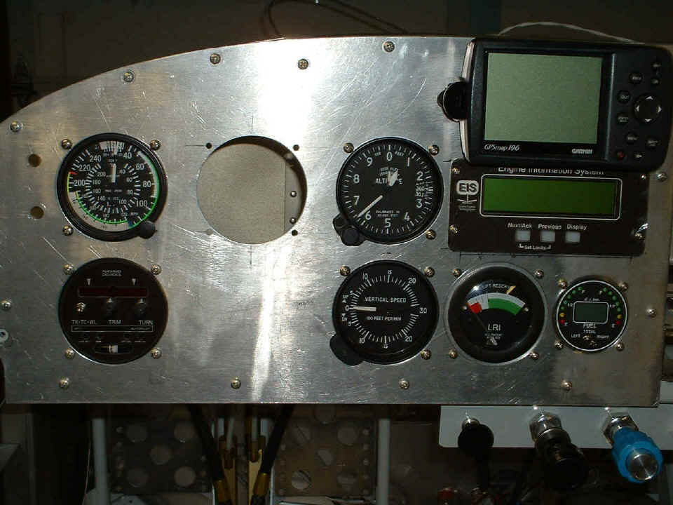
And here is the result of today's work. The missing link is the Dynon
D-10A which is expected to ship October 15th. The large blank space below is
reserved for a VOR/ILS indicator. That will come with a COM/NAV radio. After
taking this picture, I got up on a chair and looked behind the panel and realized that I
could move things around a bit and may do so yet. That would mean starting over with
a new blank panel. I don't take that move lightly since there is a lot of work in
this panel so far. I reviewed some of that today when I thought of doing it all
again. I will see how much overlap the Dynon unit has before I make that decision.
The engine monitor has a large red warning light that I will mount above the altimeter. A row of switches and breakers will go under the panel to the left of the engine control cables on another sub-panel. I am also thinking about a brace behind the control cable panel to stiffen that area. Putting this panel in place helped, but it needs more. The total work time on the airplane is 1234.5 hours. The labor including shop preparations and building work tables is 1303.5 hours.
October 1, 2004: No work on the plane for
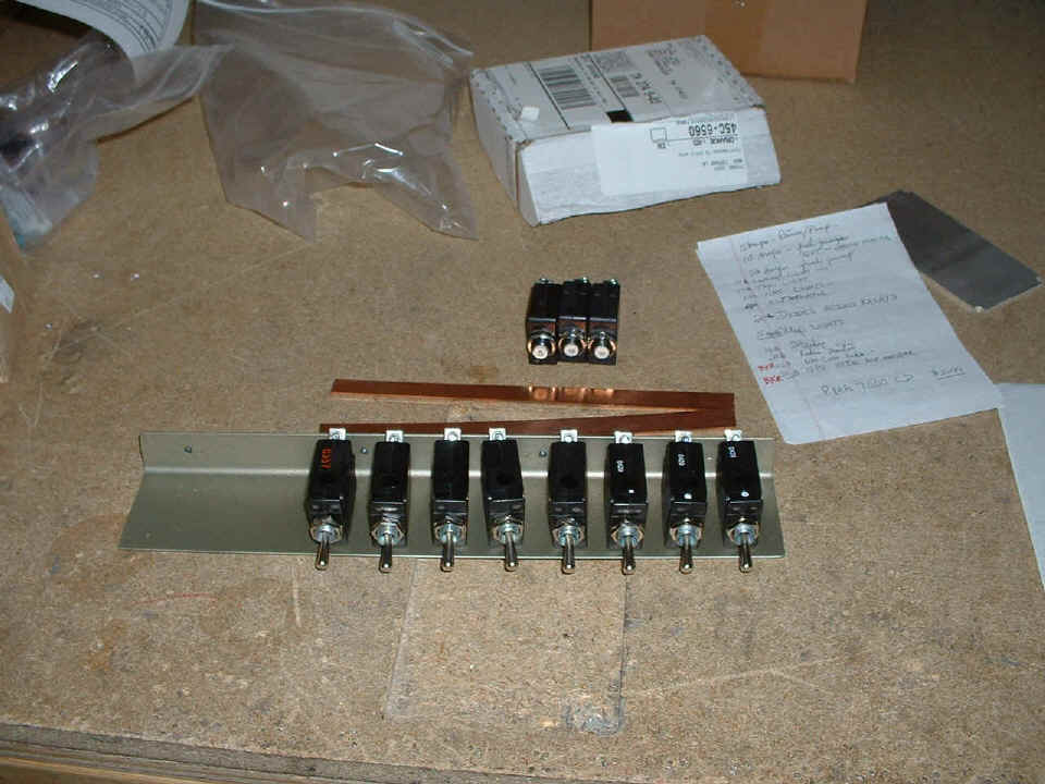
this posting, but I did receive some switch/breakers and plain old circuit breakers in the
mail from Aircraft Spruce & Specialty. Of course I had to place them on the
sub-panel that will be on the LEFT side of the throttle panel. The empty space at
the left end will get the mag/starter switch. I have not yet decided how close I am
going to have these switches mounted on the panel. I was thinking about putting a
piece of that copper bus bar across all the switches so that I only have to bring ONE
piece of number 8 wire to the breakers (or not).
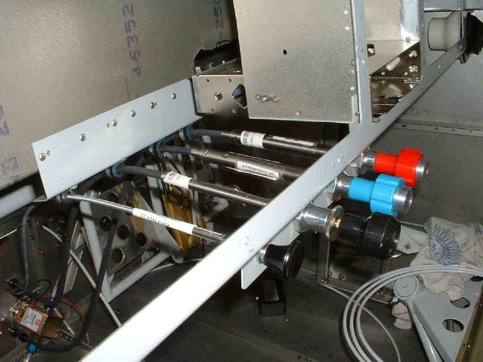
Here is a look down behind the panel adjacent to the radio stack area.
There is about 1/4" wasted space down at the bottom where the fuel gauge should have
been closer to the stack.
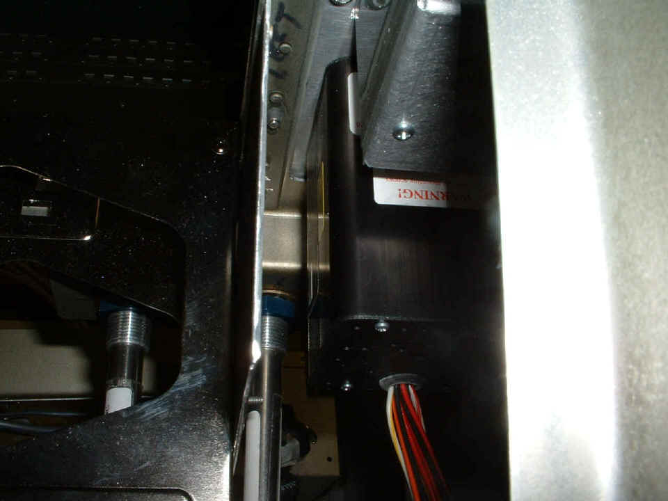
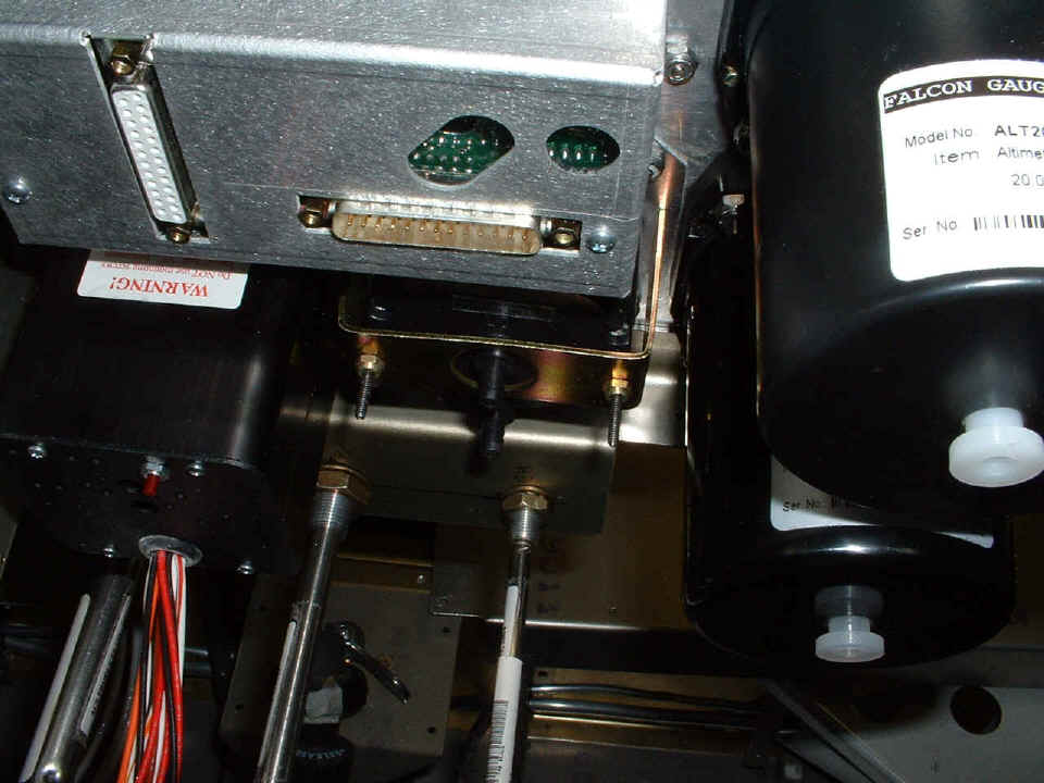
This shot reveals the "too close" condition between the VSI and the
Lift Reserve Indicator mount. Look below the engine monitor to see what I am talking
about. The red button and all those wires are on the back of the electronic fuel
gauge. The LRI has the two black air fittings sticking out the back. That is
the altimeter at the top right and the VSI at the bottom right of the photo below.
Both get plumbed to the static air only.
| CLICK HERE for Firewall Forward - Page 57. | RETURN to MAIN MENU |