FIREWALL FORWARD & WIRING - Page 50.
July 14, 2004: After finishing all the
riveting on the canopy, it was time to open one of the boxes from the firewall forward kit
and get started. The easiest thing was to take the pressure sensor manifold and
drill that to the firewall at the front of one of the top ribs. This thing will get
an oil pressure sensor switch and one or two other sensors attached to it when the time
comes.
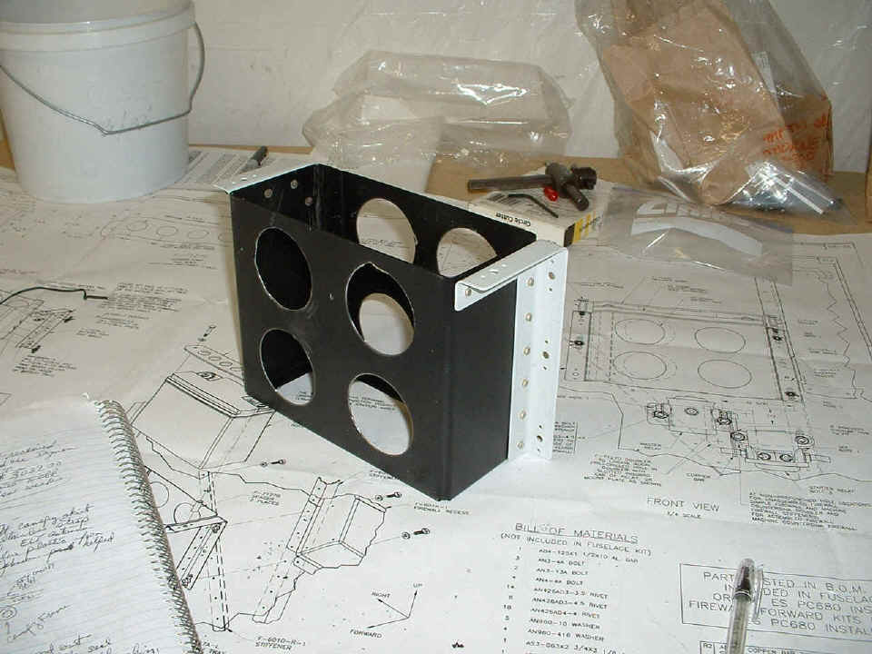
The second thing for the FF kit today was to open up some 2-inch holes to
lighten up the weight of the battery box. Since it is made of steel, not aluminum,
there was a lot of gnashing of teeth and dulling of a hole saw before I realized that the
best way to conquer this thing was in little steps with a 1/8" drill bit where the
circle fell from the hole saw through the black paint. There are more pieces to
rivet onto the box, but that is for another session...stay tuned to this channel.
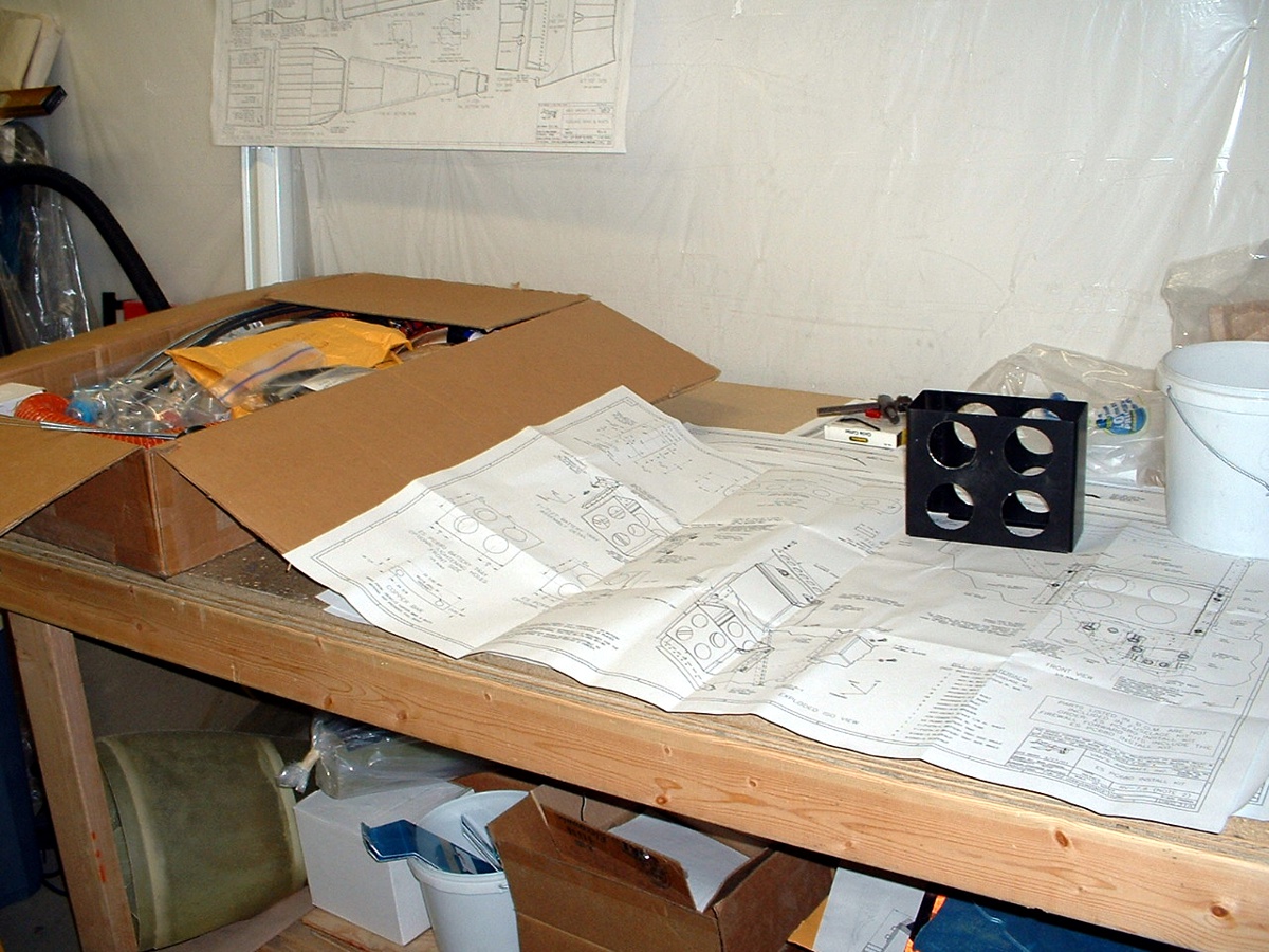
By the way, that box on the left end of the work table was repacked after I took
inventory of the kit. Most of the "stuff" that I will be using over the
next few weeks is in there. At the bottom of that box is the Vetterman Exhaust System.
As I was cleaning up some trash for garbage day tomorrow, I noticed that all the
newspaper that was used as packing came from Rapid City, SD -- near the home of Larry
Vetterman. That box was the one used to ship the exhaust pipes to Van's. It
had a lot of other things added to it along with more packing and then it was shipped to
me along with another bigger box that had things inside like the filtered air box, engine
cooling baffles, and a 60-ampere alternator. That alternator is in the white box at
the left end of the shelf at the bottom of the picture above.
| NOTE: I went off to Oshkosh and did some other things like putting in the Tugwell canopy opening cable modification during this time. You can go to those pages to see other things that happened to the canopy during this time frame. After you finish those FOUR pages, a link at the bottom of the last page will bring you back HERE. This page was edited on August 20, 2004 to get things back on subject: Firewall Forward! |
August 12, 2004: I have returned from Florida due to a change in plans. It had something to do with a tropical storm and a hurricane threatening Florida. Since I could work at home and did not want to get caught in an evacuation of parts of Florida, I left Miami Tuesday afternoon and drove up to Ocala, Florida to spend the night. I got home late Wednesday afternoon, August 11th. I claimed my mail at the post office Thursday morning and found two boxes waiting for me. One was from InAir Instruments and contained my Lift Reserve Indicator that will serve as a visual stall warning indicator on my instrument panel. The other box was from SafeAir1 and contained my ELT and a wiring harness for the Dynon EFIS-D10A. The Dynon unit and the other accessories will ship factory-direct in a few weeks. I will post pix when it arrives.
August 15, 2004: I can now turn my attention
back to the front end of the airplane. Here are two pix to show that. The
steel battery box had previously been drilled with lightening holes to save weight.
Now it has the mounting brackets match-drilled and riveted in place.
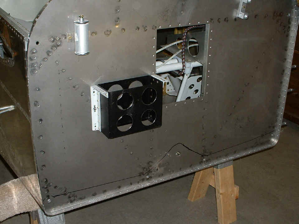
The battery box is now drilled to the firewall and I called it a night around 9 PM
in order to have time to post this pages and the new pictures and text back on page 51.
I also ordered the Odyssey PC-680 battery tonight. The
total construction time on the airplane is now at 1260.4 hours.
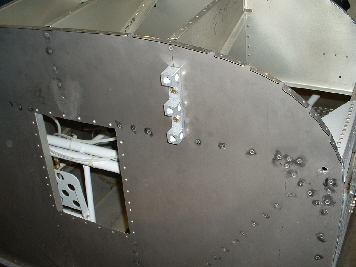
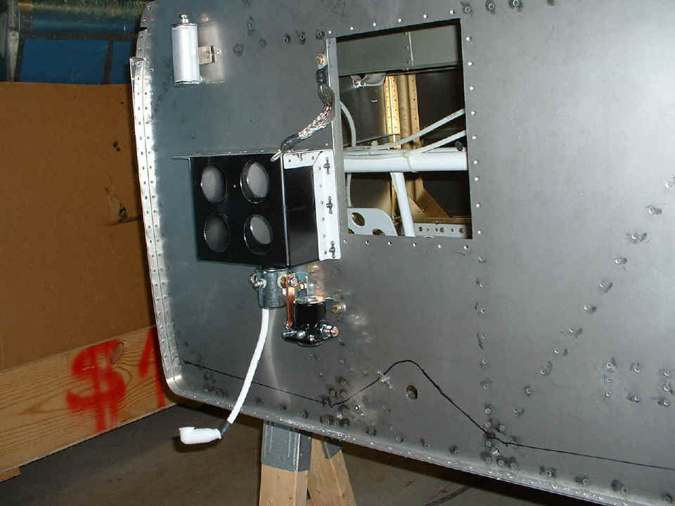
August 16, 2004: I managed a couple of hours
tonight to get the battery hold down strap built, then fabricated a doubler plate to mount
solenoids for the master switch and starter. I have temporarily attached the ground
and positive cables to the appropriate places. You can also see the two copper bus
bars that I made to connect from the master solenoid to the starter solenoid. Van's
designed the mounting of the starter solenoid so that positive "G-forces" cannot
close the starter solenoid contacts. The PC-680 battery shipped today from
Jacksonville, Florida and should be here on Wednesday the 18th. There is also a
battery charger ordered as well. This was the day I ordered the Garmin GTX-327 radar transponder, a
blind encoder, radar antenna, and coax. All those items are from LaFayette Avionics in Indiana.
Add another 3.7 hours to my total work time.
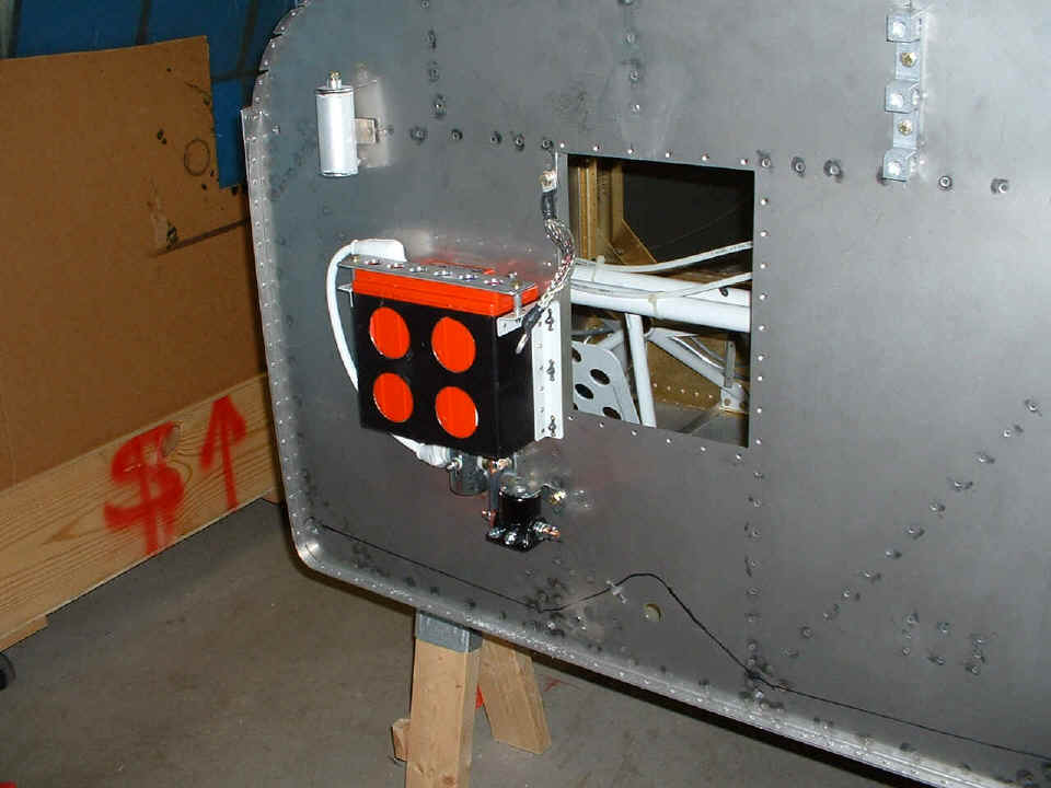
August 18, 2004: The
battery I ordered has arrived via UPS from Jacksonville, Florida. As you can see, I
have it installed and only the positive terminal is installed. I also cut the
aluminum tube spacers that keep the hold down strap from pushing down hard on the battery
case. The negative terminal is disconnected from the battery for now. I
checked the voltage and it reads 12.76 volts. The shop charger that I ordered is due
to be here tomorrow. I also checked the master switch solenoid and it works of
course. I ground off a little bit of one mounting ear of the master solenoid to
allow for a perfect vertical alignment of the copper bus bar going down to the starter
solenoid. I started to look at the various wires provided in Van's wiring harness
kit and have counted the fuse blocks needed, number of switches, etc. More stuff to
acquire...
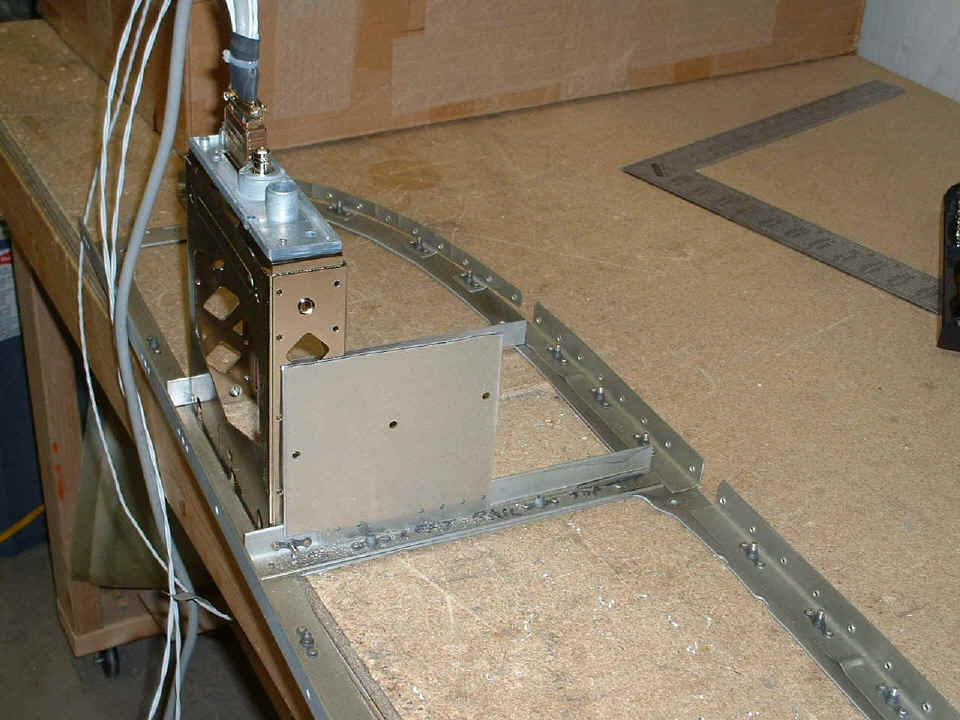
August 21, 2004: A short work period today
where I removed the instrument panel frame from the fuselage and installed the second rail
for mounting the radio stack. I was waiting until I had a radio tray to do this
job. My thinking was correct. I found that my cuts into Van's original panel
were "less than perfect". I did some filing on the edge that already
had an angle riveted in place. I also needed to file along the top half of the right
side of the radio stack opening to make the two sides parallel. I am still working
to get the side brace panels on the Garmin 327 mounting tray to hold the rear of it
steady. Here is how I left it at the end of the day. You can see the #6 screw
sticking through the platenut near the bottom of the rail on this side of the tray.
That panel with the holes in it sitting along side the transponder tray is 1/2 of the
"big battery" tray that came with the kit and I am not using it as a battery
tray (obviously). Of the six rivet holes already punched in the panel, I will
probably use three of them to attach the panel to the mounting rail. What you don't
see is another screw hole similar to the one near the aft end of tray on this side.
That hidden screw hole is the one that will be aligned with a new hole and #6 platenut in
the panel below. I have another panel already made from the other half of the
battery tray that will go on the other side rail of the radio stack. I should finish
all that work tomorrow and you will see the pictures then.
| CLICK HERE for page 51. | RETURN to MAIN MENU |