FIREWALL FORWARD & WIRING - Page 51.
Why are firewall forward and wiring linked together? After putting that battery on the firewall, there has to be something connected to it. The first thing going in that needs electricity is the radar transponder. So you will see virtually every thing else I do in this section of the web site until I take the airplane to the airport for final assembly and flight testing.
August 22, 2004: It is time to put the tray
for the radar transponder in the panel. Here are the results after putting in a few
rivets and some platenuts to secure the tray to the side panels. I had to use my
Dremel tool to grind a little bit of clearance for the locking tab that holds the unit
firmly in the tray.
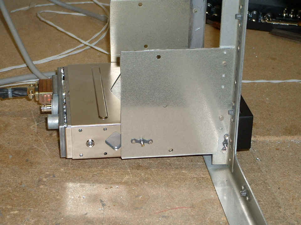
Here is a side-view showing the #6 platenut and screw that holds the rear of
the mounting tray secure. I think I will go ahead and put a second rivet in each
side of the panel and the forward mounting rail near the top of the side panel.
These are #4 flat head rivets with the flush heads on the inside of the rails. You
are seeing the shop heads on this side. I used my rivet squeezer to put these rivets
in place.
This photo shows a little of the notch I cut with my Dremel rotary file under
the center of the transponder. This was to allow the locking tab to clear the
instrument panel front face. You can see where I have scratched the paint when I had
the frame clamped in my vice mounting the second rail and the transponder mounting tray.
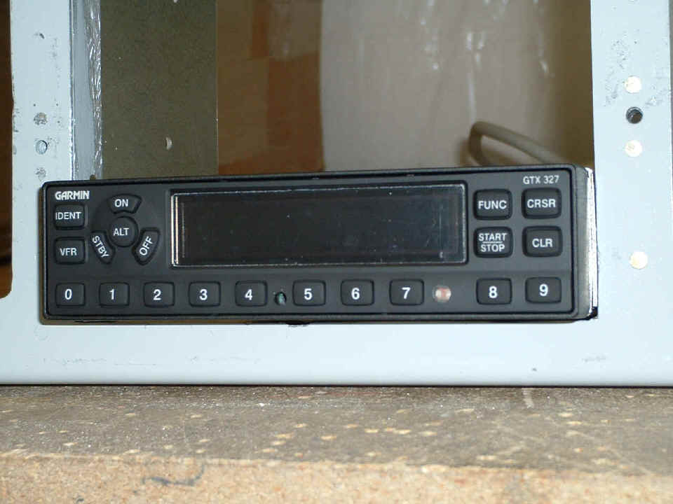
Without the transponder in place, the grinding is easier to see. I
actually took out just a bit more of the front panel at this location after I took this
photograph.
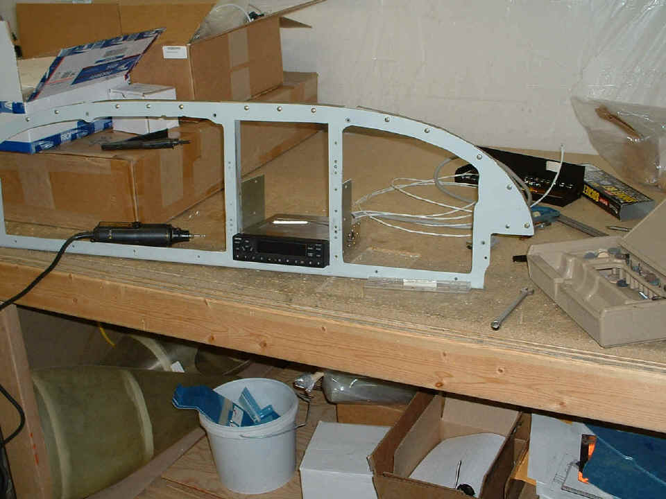
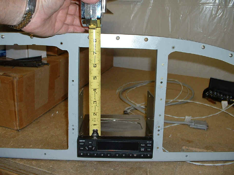
So what next? The thought occurred to me "How much remaining space
do I have in this radio stack?" The answer is about 5.25 inches above the
transponder. No, that was not planned, it just happened that way.
Now to get this thing back where it belongs. After some drilling on the
sub-panels behind the instrument panel, then some hand-nibbling, filing, and sanding the
edges with my Dremel sanding drum, I have restored the two main panels to the instrument
frame to be sure that everything fits in the proper places. Notice that the two
panels are secured with all the mounting screws. The GPS 196 is not there of course,
and the Dynon unit won't be here for several more weeks. Now that I am satisfied
that the Garmin GTX-327 transponder fits in its place at the bottom of the
"stack", I can start planning to remove all the instruments from the left
sub-panel to put in the other items as they arrive.
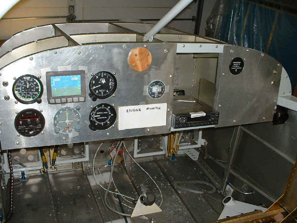
I found some add-on instrument lighting rings at OSH this year. I have to
see about getting some of those on order. I really want to put that engine monitor
in before I do much of anything else. Of course, if I mess this panel up, there is
still enough of that "men working" aluminum road sign remaining to build at
least two more panels.
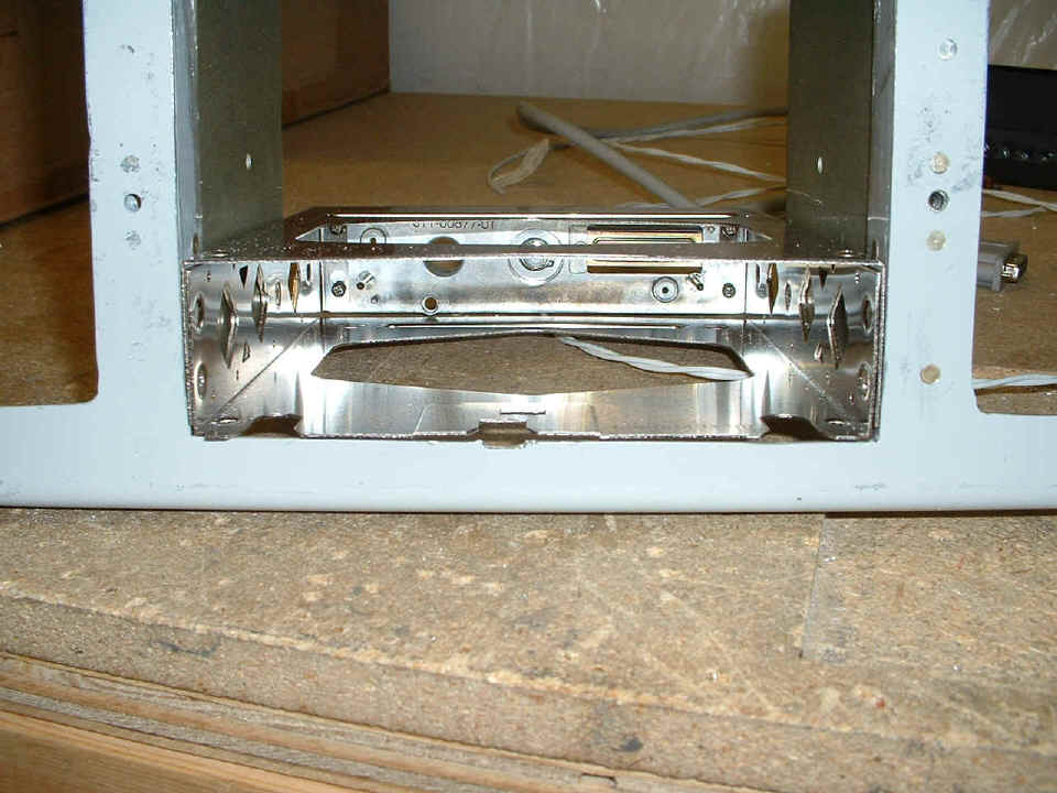
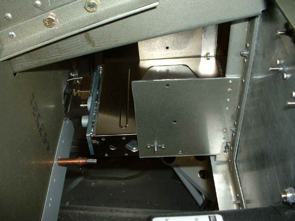
And here is a look behind the panel showing the clearance hole I had to cut in
the back panel. That is the BNC antenna connection near this side of the access
hole. The connection to/from the blind encoder is the 15-pin "D-connector"
that is just a bit further away from the camera. And yes, when the two instrument
panels are removed from the frame, I will be able to put in those two extra rivets I
mentioned in the side panels securing the radio stack trays. And no, I don't plan on
putting any more #6 platenuts through the side panels and any other trays that stack on
top of the transponder tray. I will probably just put the one at the front rail that
would go through the side panel, or just drill a clearance hole and use flat-head #6
screws, a nut and washer on the back side of the stack rails to keep the add-on trays in
place.
The total work time on the aircraft now stands at 1173.0 hours.
| CLICK HERE for Firewall Forward Page 52. | RETURN to MAIN MENU |