FUSELAGE CONSTRUCTION - Page 28.
October 24, 2003: SEATS!
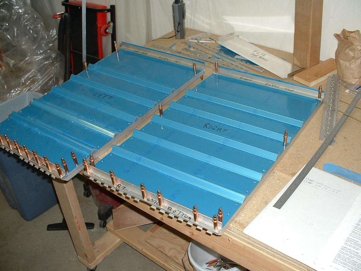
At least that is what I worked on today. I managed to finish both seat backs
in sessions today. I had already finished match-drilling all the holes in the aft
top skins in an earlier session and removed the skins. I also finished the aft
baggage bulkhead panels as you can see in the second picture. That was the same
session where I put the baggage floor in and riveted it in place.
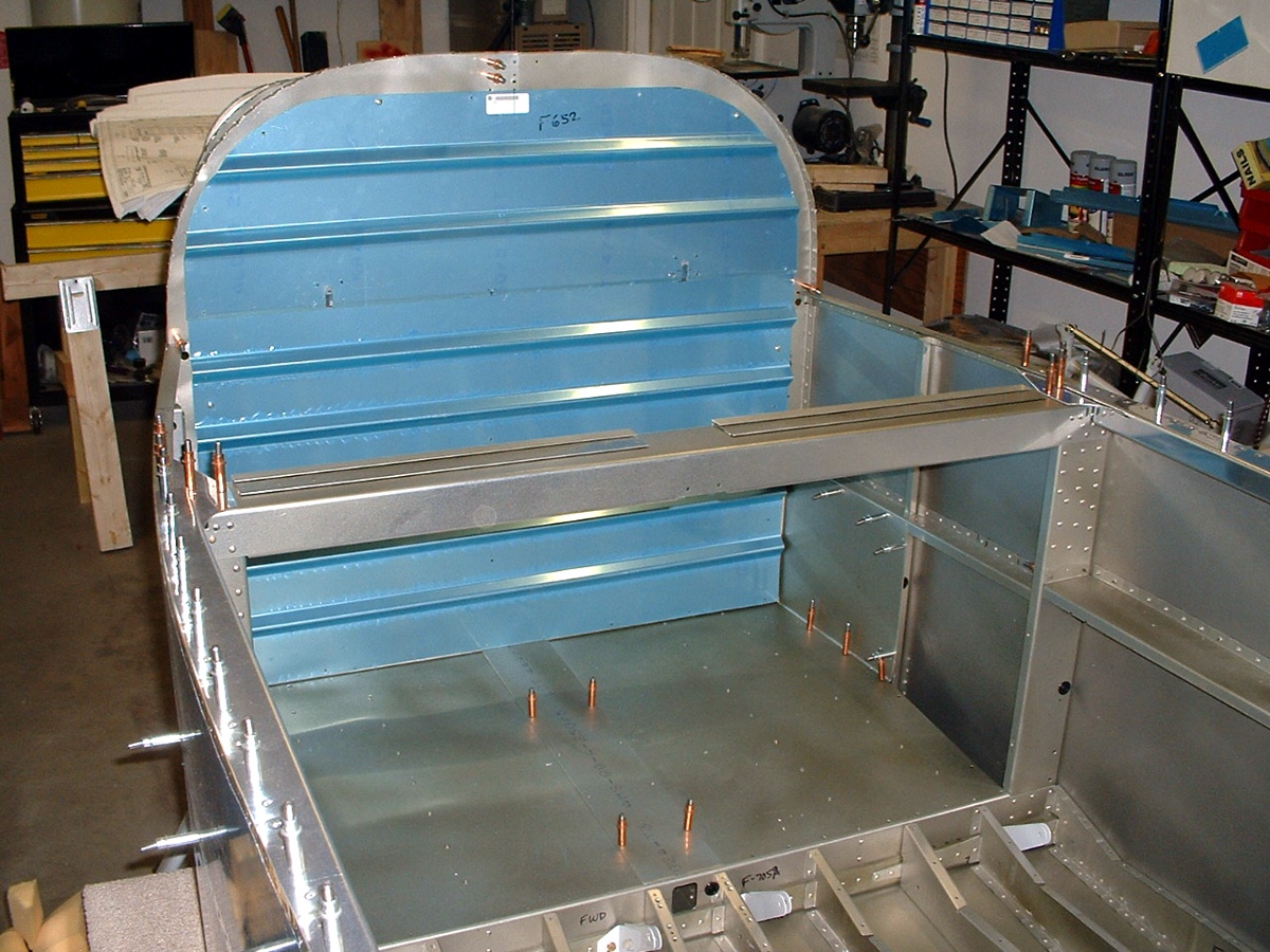
The clecos in the center are holding down the baggage tunnel cover. The
clecos along the wall hold the rear side baggage panel in place. The elevator
push-rod, the elevator trim cable, and wiring go in the baggage tunnel. The rudder
cables still have to be threaded through those black plastic bushings you see in the side
wall. After the rudder cables are in place, then I will rivet the side panels in
place. The baggage tunnel cover will be held in place with screws when the work in
there is completed.
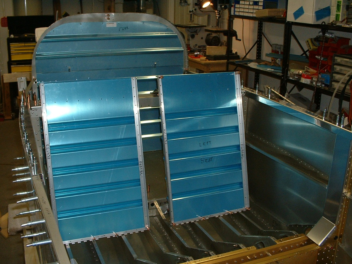
October 25, 2003: I finished the back braces
that adjust the seat recline and just had to put them in place, even though the seat
floors and the hinges are not in place as you can see here.
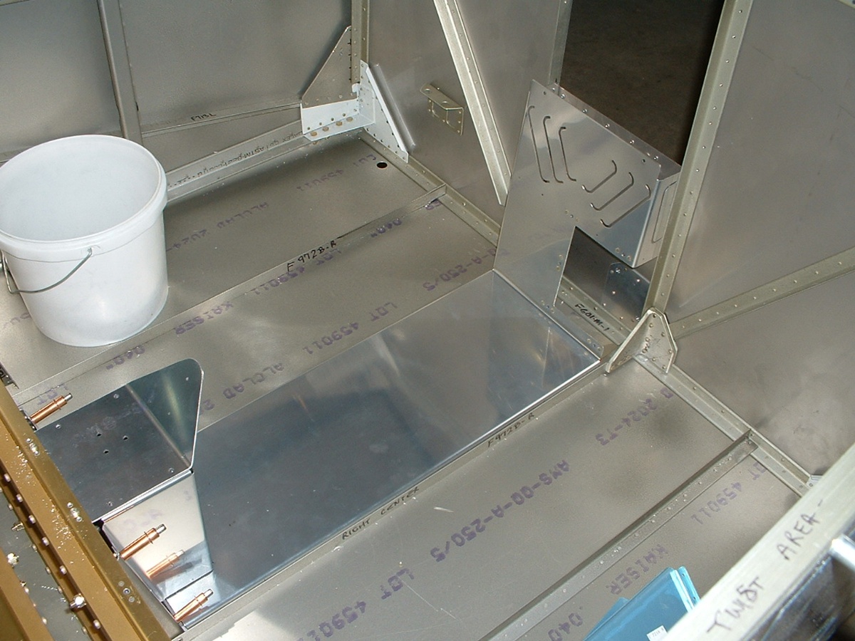
The front covers to protect the fuel tank selector valve and the fuel lines
were the next steps in the instruction manual. That flat plate with the triangular
bent area is of course for mounting of the elevator trim cable and the fuel selector valve
as seen on page 15 in David Edgemon's RV-9A.
October 28, 2003: It has been ONE YEAR today since UPS delivered the empennage kit and I started to put this airplane together. The total construction time on the airplane now stands at 876.2 hours. Other preparatory work time building jigs, fixtures, work benches totals 62.7 hours. That gives a total time of 938.9 hours on the project.
The new milestone for today was getting the landing gear sockets bolted to the
wing spar bulkhead. I have 10 more bolts to drill into the lower longerons tomorrow
and countersink the two holes on each side that I back-drilled during the installation
today. I have also been working on the flap actuator system, but did not take any
pictures of those parts when they were installed. I have since removed them for
priming, and will take photos when they are put back in later in the assembly process.
Here is the landing gear shot from just over the top of the firewall, looking aft
and down at the main bulkheads that connect the wings to the fuselage.
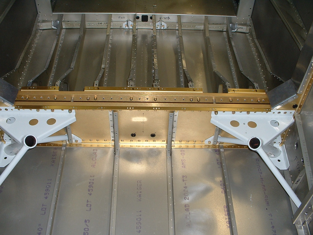
The above picture does not show it well, but there is another bulkhead there, with
a 1 7/16" spacer in between
them. I had to put washers and nuts on the bolts that I put through the steel
weldments in between the bulkheads. There were three bolts down deep on each side
that required a bit of skill to get in there. How did I do it? My hemostats
were too short, so I improvised. I took a coat hanger and bent a short right-angle
bend at the end of the wire to put the washers on the bolts sticking through the main
bulkheads. Then I took a clothespin to hold the nut, while using a second
custom-bent coat hanger wire to hold the clothespin in the correct position at the
threaded end of the bolt. Then I just turned the bolt with my ratchet wrench to get
the nut started on the bolt.
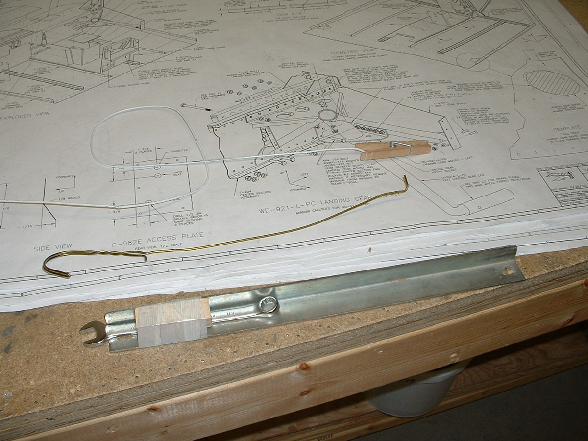
Once the nut was threaded onto the bolt, I needed a really
long 7/16" wrench, so I used some glass filament tape, a small wooden block
and a piece of steel angle to do the job of holding the nut when I tightened the bolts
through the F904A wing spar bulkhead. I decided to leave this picture a bit larger
to show the details of my improvised tools. You can see on the print that I still
have more bolts to put in tomorrow, but those are at the top of the bulkhead and along the
side wall and are easy to put in place.
| CLICK HERE for fuselage page 29. | RETURN to MAIN MENU |