FUSELAGE CONSTRUCTION - Page 29.
October 30, 2003: The big deal today was
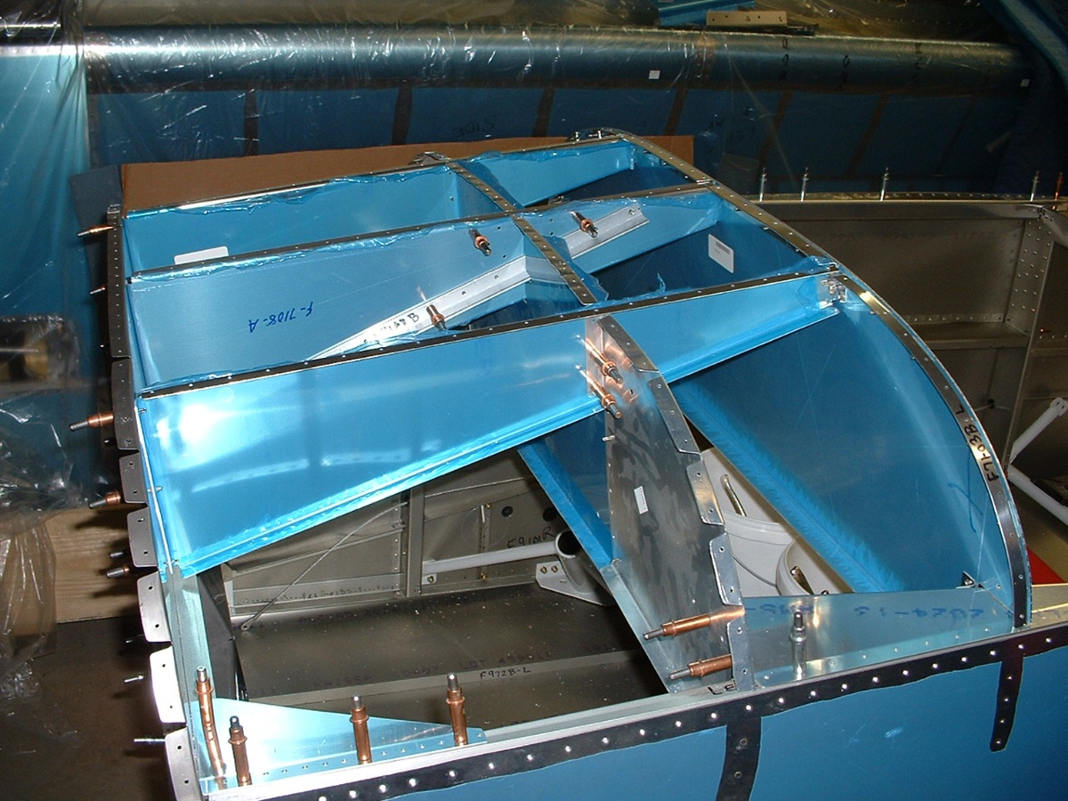
getting the blank instrument panel, the supporting ribs and the front top skin in place.
I have match-drilled the skin to the ribs, upper longerons, and the firewall.
It was another of those milestone moments. I will be getting all the top
skins ready for the next priming session.
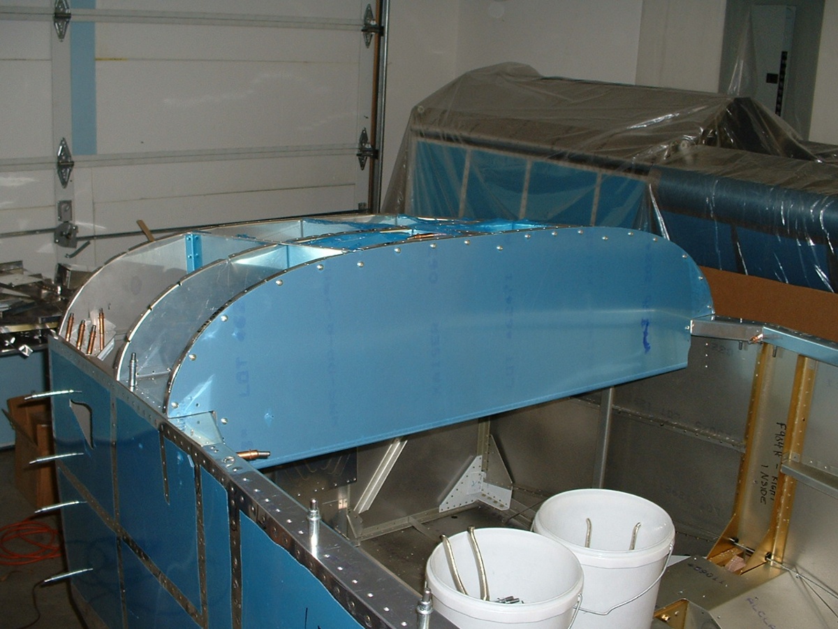
Remember the two "wrong" parts sent to me with the shipment of
the fuselage kit? The photo below shows one of the correct parts without
blue plastic, installed for the match-drilling of the forward top skin to the
ribs.
November 4, 2003: I spent this past Saturday
priming many parts of my RV-9A in preparation for my next work session. I am on the
road this week for the company and will not be working on the airplane. I did begin
my travels with a side trip to Huntsville, Alabama Sunday afternoon to see my friend David Edgemon and his new Superior "Lycoming clone"
engine custom-built by AeroSport
Power. Here are some photos from my 2-hour visit with David on Sunday, November
2nd. This is an O-320-D1A with one magneto and one solid state ignition still
mounted to the shipping skid after removal of the outer crating panels. It is set up
for a variable-pitch propeller. All the accessories have not yet been mounted.
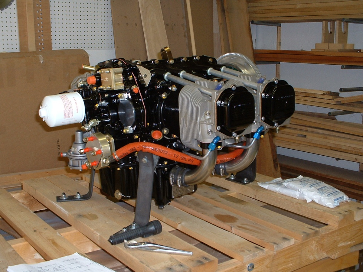
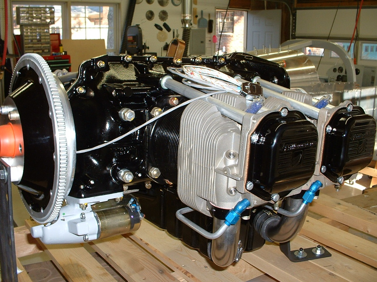
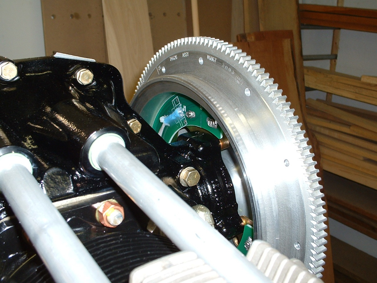
On this side of the engine, you can see the starter and the sensor wire coming
from the flywheel sensors to control the solid-state ignition system. For those of
you not familiar with aircraft engines, this model of 4-cylinder Lycoming engine is used
in many Cessna 172 aircraft and has two sets of spark plugs. One set is connected to
a magneto, and the second set is connected to the solid-state ignition system. That
solid-state ignition improves the fuel economy by as much as 15%. Automotive spark
plugs with adapter sleeves are used with the solid-state ignition.
And here is that ignition crank angle sensor board behind the flywheel.
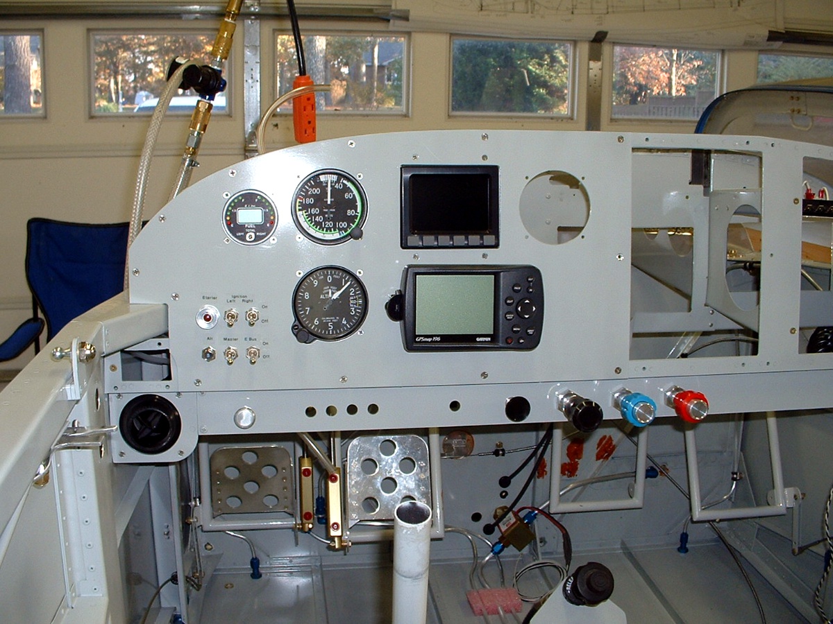
Here is the current status of David's instrument panel. He liked my
Garmin 196 and bought one for himself. The blacked-out screen above the Garmin GPS
is a Dynon D-10 multi-function flight instrument which incorporates an artificial horizon,
turn-and-bank coordinator, magnetic compass, altimeter, vertical speed indicator, and
angle-of-attack indicator. It can also display DC voltage. David has also put
in a traditional airspeed indicator and altimeter to go along with the dual fuel
gauge indicator with LED and LCD readout. The empty round hole is for an auto-pilot to be
added later. The radio stack will have an electronic engine monitor, communications
radio, and radar transponder. The four knobs in the center of the bottom panel are
for carburetor heat, throttle, propeller control, and fuel mixture control.
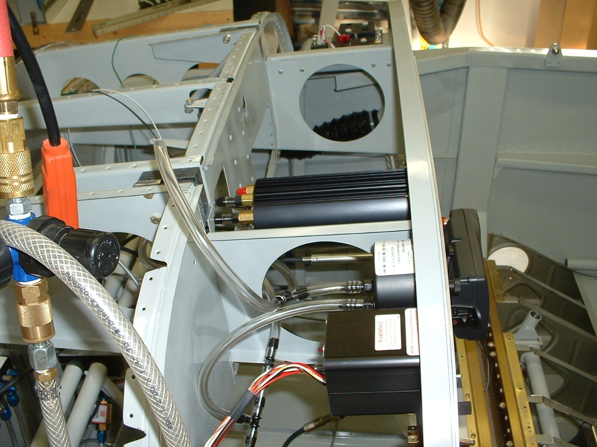
Here is a look behind the panel at the plastic tubing plumbing from the pitot
tube and static port feeding the instruments. The short tube going up in the air is
used to test for airspeed for now and will eventually be connected to the pitot tube.
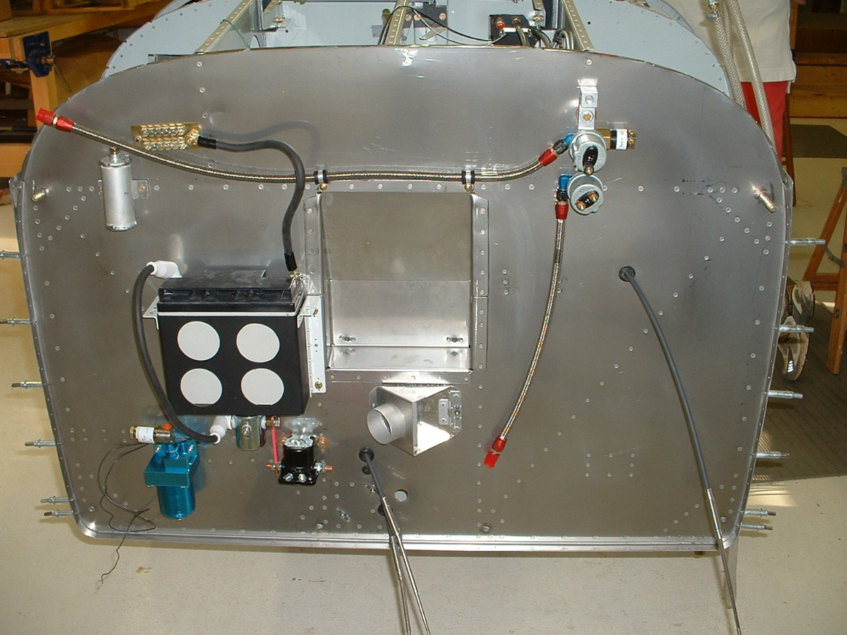
The firewall photo reveals the beginnings of things to come. The battery
is at left center with four "lightening holes" cut in its support to reduce
weight. That blue thing is the gascolator to help separate water from the fuel
before it reaches the engine-driven fuel pump. There are two solenoids right under
the battery -- one for the main battery bus, the other for the starter.
| CLICK HERE for fuselage page 30. | RETURN to MAIN MENU |