WING KIT CONSTRUCTION - Photo Page 15.
July 31, 2003: I called Van's Aircraft in
Oregon today to check on my fuselage shipment. The kit ships on Friday, August 1
according to Anne B. I also purchased the Navaid
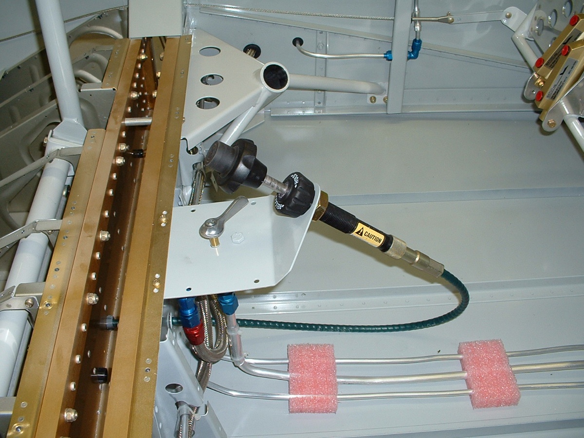
Devices wing leveler/turn coordinator today. I spent three hours figuring out
how to mount the servo adjacent to the aileron bellcrank and fabricating a mounting plate
for it. There are some pictures below. This is a work in progress which will
require me to also make a bracket to interface at the bellcrank. I have to decide on
the amount of movement that is required to take the stick through full aileron deflection.
The interface linkage and the attachment points for it must not push the servo past
its mechanical limits with full aileron movement.
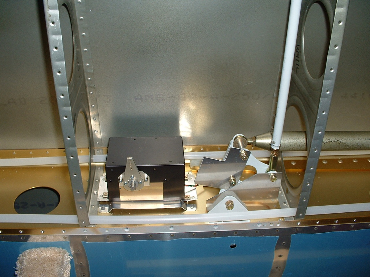
The servo mounting plate is riveted to the spar with four blind rivets.
There are four #6 plate nuts and screws holding the servo to the mounting plate. I have to
finalize the shape of that interface plate that is attached to the aileron bellcrank with
the two bolts and then attach the linkage between the servo arm and the interface
plate. I will cleco on the bottom skin and be sure I can work on this thing via the
access plate. And yes, that is the aileron calibration jig bolted in to verify the
center of aileron movement. Now that the servo is mounted, I will probably wait to
complete the linkage attachment when the fuselage is ready to mount the wings and check on
the aileron movement from the control stick in the cabin.
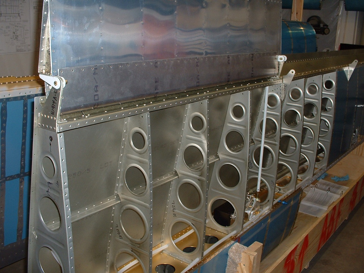
Below is the view from the end of the wing showing the aileron attached to the LEFT wing again for this
trial fit of the wing leveler servo. The servo is the black object visible through the
large lightening hole in the fourth rib from this end. The gray steel rod running
vertically is attached to the bellcrank and the aileron hinge assembly. You can also
see the large aileron push-rod that runs from the bellcrank toward the fuselage passing
through all the other large rib lightening holes.
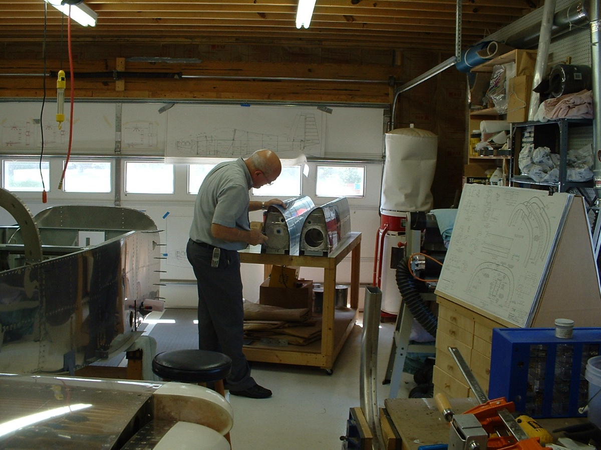
August 3, 2003: I went
over to the Huntsville, Alabama area to work with my friend David
Edgemon on my fuel tanks. He showed me a safe and easy way to pressure test
the tanks without the possibility of any damage to them. The RIGHT fuel tank was
fine, but the LEFT tank had a leak in the corner at the fuel filler end of the rear baffle
plate. Some sealant was applied by reaching inside the tank filler neck with a bent
brush to put the sealant in the correct place filling the hole. David managed to get
this picture without my knowledge while I was putting the end plates on the fuel tanks
before the pressure testing.
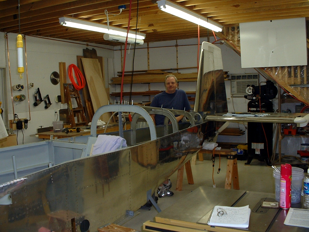
You can see the forward part of his RV-9 fuselage in the left center of this
picture. The tip of the horizontal stabilizer and the tip of the RIGHT elevator are
visible in the bottom left corner of the photo.
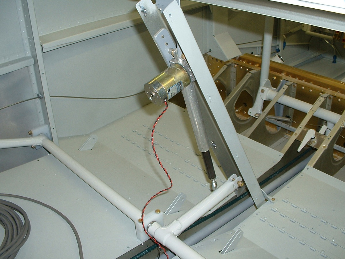
Here are some pictures of David's RV-9A. The elevator push rod is
connected from the control sticks to the elevator. He has just rigged the rudder
cables to the rudder control arms. You can see he has the pilot's seat temporarily
installed with some cushions.
Here is the elevator trim control cable and the fuel
tank selector handle in David's fuselage. It is mounted to the wing spar
carry-through assembly. The large aluminum tube on the floor is the fuel line going
to the electric fuel pump. The two smaller tubes are brake lines.
Here is the flap actuator and the steel control rod that connects to both
flaps. That lever between the control sticks is the manual aileron trim control with
its springs connected to the aileron control linkage.
August 4, 2003: No pictures today, but good
news from Barb at Van's Aircraft -- the fuselage shipped today from their facility via ABF
motor freight. I managed to find a second leak in the LEFT fuel tank and will be
sealing that one and the end plates and cork gaskets in my next session. I also
spent 1.5 hours today putting the fiberglass tips on both elevators. Total aircraft construction time now stands at 551.3 hours.