Wendell Folks RV-8 Project - Page 39.
January 13, 2007: The Saturday session
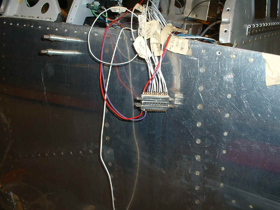
provided a pschological milestone for Wendell as the wiring and air plumbing made some
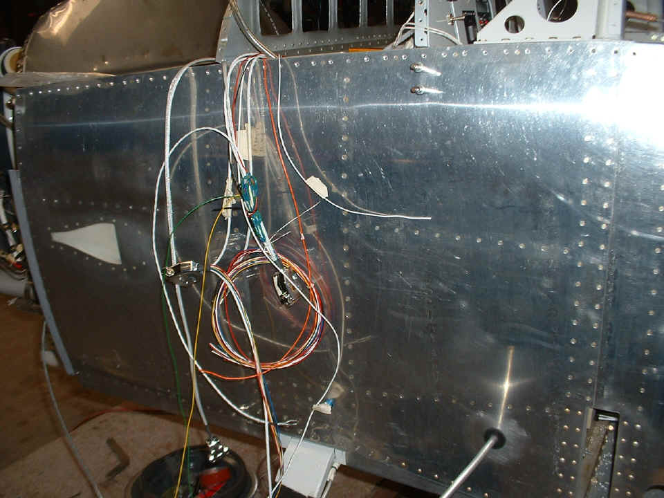
headway. The power wires to the various items on the removable instrument panel are
starting to come together on one pair of DBM-25 plugs. The plugs and sockets will
permit easy removal of the instrument panel for long-term maintenance when needed.
The red wire carries +12 volts to one side of the alarm light from the engine monitor,
while the purple wire connects to the negative side of the light. The white wires
provide power to the GPS, NAV, COM, radar transponder, audio panel, and control the oil
pressure light from the pressure switch mounted on the firewall. There are still a
few more wires to add to this pair of DBM connectors. Although it does not show in
this photo, Wendell finally riveted the 6-32 platenuts that will secure each basket to the
radio stack mounting rails.
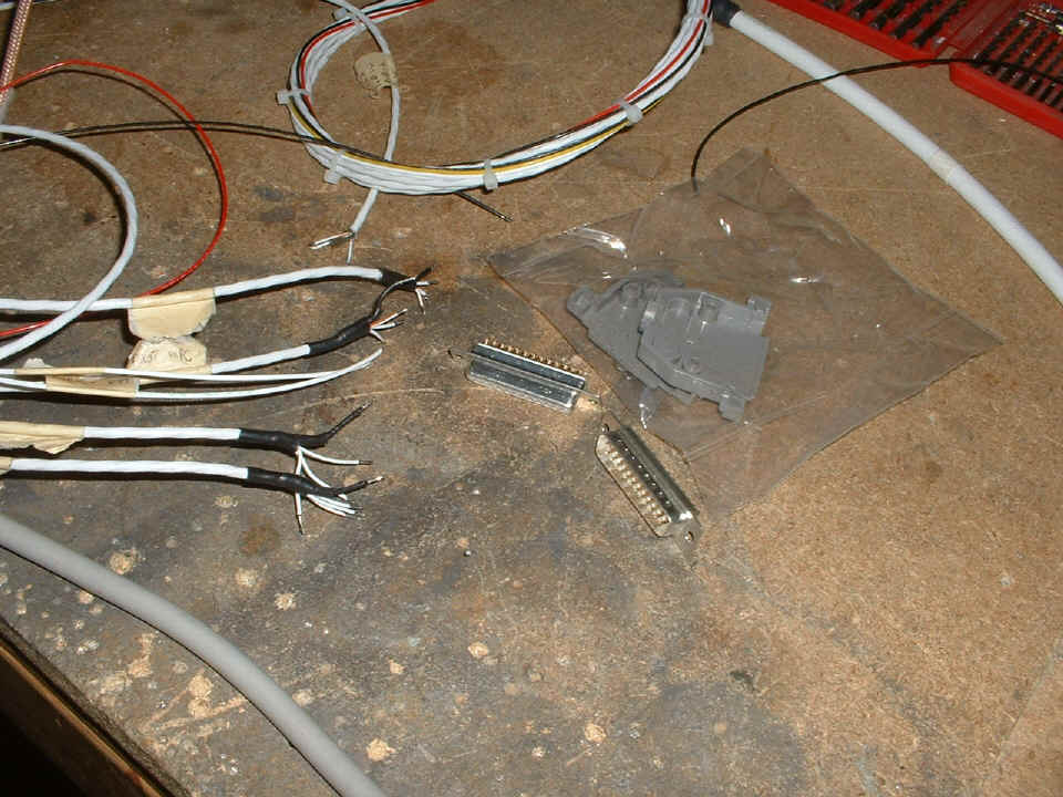
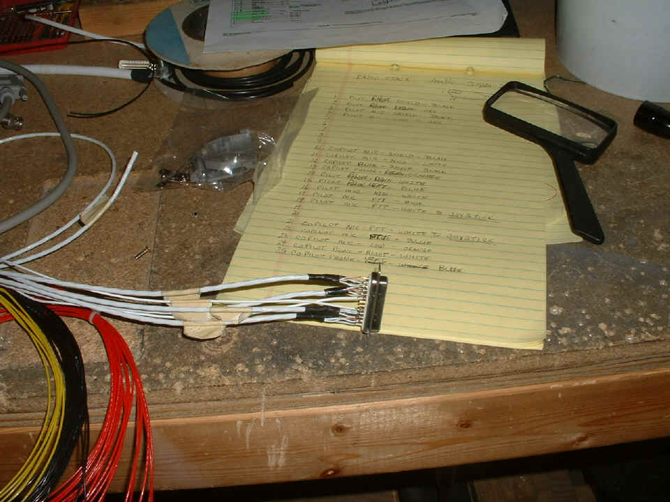
Over on the work bench, the radio stack is getting the same DBM-25 connector
treatment for the headphone and microphone audio circuits and the push-to-talk wires that
will connect to the stick grips. Each cable came from Pacific Coast Avonics with a
tape label near the free end of the cable. We determined at what point away from the
radio stack the connectors would be installed, then made more labels to put on each side
of that cut location. Here you see the preparation work with heat shrink over the
shield wire connections. When completed, these audio connections will have GRAY
connector shields. The connectors pictured in the photo above will have BLACK
plastic connector shields. They will also be configured so that the two connectors
attached to the removable instrument panel can only be plugged into the mating connectors
that are soldered to the fuselage wiring. A female DBM-25 connector will be soldered
to the audio wires from the radio stack shown in the photo below. A male DBM-25
connector from the instrument panel will mate with the female power connections shown in
the photo above.
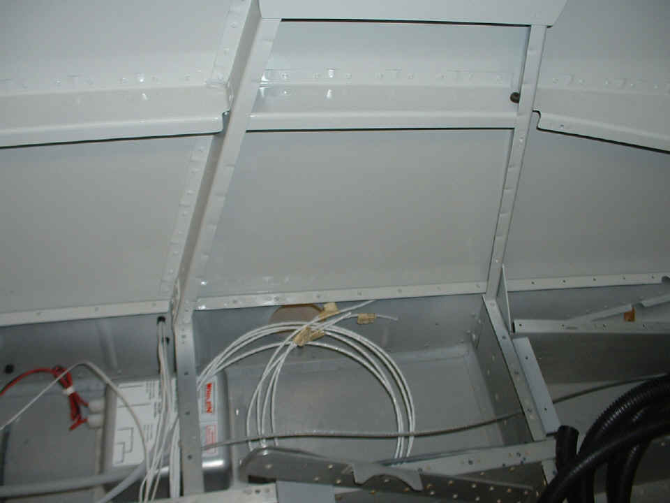
While I was preparing the heat shrink on the wiring on the work bench, the
other ends of the headphone and microphone cables were being installed in the fuselage by
Wendell. This is a view of the right side of the fuselage between the seat
locations. These cables will come up the side wall with the mating microphone and
headphone jacks mounted on the bulkheads near the top of the photo below.
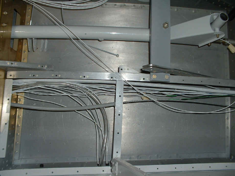
The photo below is looking down at the wiring and the pitot tube Tygon clear
plastic air line on the LEFT side of the fuselage. There is one more coaxial cable
to be installed before all these wires are bundled for final installation positioning.
The aileron pushrod from the control stick assembly will pass below all these wires
and the pitot air line. The two wires running from the top left corner of the photo
toward the right center of the photo are the push-to-talk wires that will connect to the
control stick assembly and the stick grip switches.
Up by the instrument panel, the free ends of the wiring harnesses for the Dynon
D10A and the two Trio controllers await their connections to the control heads in the
panel. The free end of the Tygon pitot tube is visible. One of the two plastic
air lines from the LRI probe is just visible behind the panel. When all the wiring
and air line plumbing is finally mated to the instrument panel components, it will be time
for a celebratory photo. Then everything must be removed to make way for the
riveting of the top forward skin to the fuselage and all the mechanical assembly work that
will follow that milestone.
January 14, 2007: The
Sunday afternoon session began around 1 PM with my arrival at Wendell's shop. The
wind was gusting enough that I did not want to go flying right away, so I went to work on
the audio wiring connections plugs. Wendell is not good with the soldering iron and
has asked that I do this type of tedious work. Each cable with multiple wires inside
is tagged and each wire and its pin connection is entered in the chart by function and
color codes. The push-to-talk wires that run to the joy sticks are also fed through
this DBM-25 connector.
While I was sitting at the bench working, I had Wendell riveting in the side support plates and #6 platenuts to the radio stack mounting rails. Now that those items are installed, the actual radio stack baskets can be mounted to the instrument panel. We also had a detailed discussion about the best way to route the coaxial cables to the various antennas. They are a bent-whip COM antenna and a radar transponder antenna under the pilot seating area, 75 MHz marker beacon antenna just ahead of the battery (also on the underside). The ELT mounting location was also decided. It will end up inside the aft-most baggage area on the RIGHT side of the fuselage. There are unused holes in the bulkheads back there for routing the coaxial cable to the antenna which may end up on the top of the fuselage just forward of the vertical stabilizer. An alternate ELT antenna location adjacent to the rear seat passenger on the arm rest is also possible.
The assignment for Wendell for the next few days is to get the various coaxial cables installed, plus mount the radio stack baskets and all the flight instruments in the main panel. We also spent some time online today placing an order to Aircraft Spruce & Specialty for the additional and spare circuit breakers we need to complete the electrical wiring. Wendell also wanted to order Epoxy resin and and hardener, the 9-ounce fiberglass cloth, and an engine oil quick-drain plug. When the wiring is completed, it will be time to start configuring the airplane for the installation of the forward top skin to the fuselage. After that, installing the propeller, cowl, and windshield will be foremost on Wendell's mind as we go forward. He is getting excited as more milestones are achieved in the project.
| CLICK for Folks PAGE 40 | Return to Other RV Menu | Return to Main Menu Page. |