Wendell Folks RV-8 Project - Page 40.
January 15, 2007: The Monday evening session
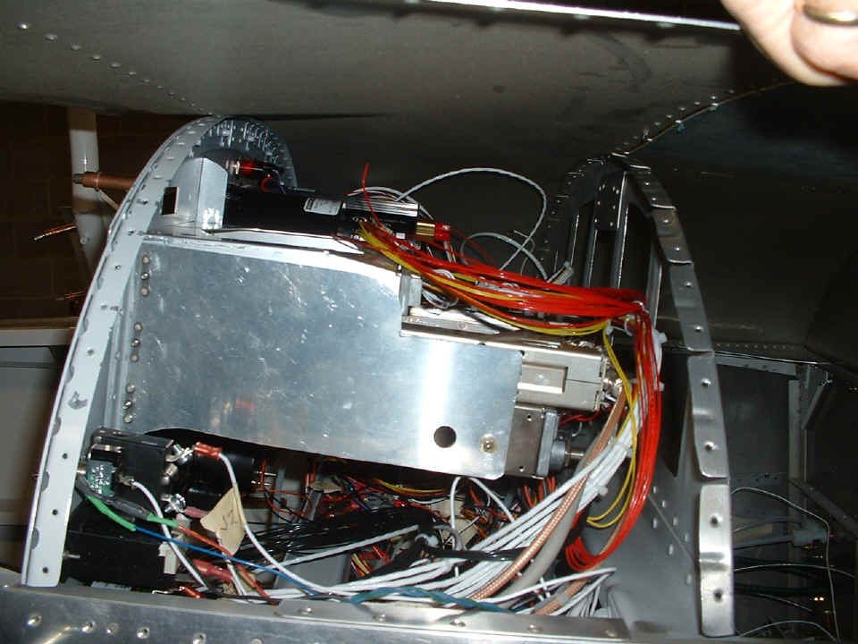
saw the instrument panel fully loaded and installed in the fuselage for a fitting to
determine cable clearance from the next bulkhead and the radio stack. Here is a peek
under the hood with the panel in place and the forward top skin partially clecoed into
position to establish bulkhead positions. With everything in these positions, it did
not take long to determine cable bundle placements that will be needed. The only
thing missing from the panel is the ELT remote control panel. When all the wiring is
completed, the instrument panel and the items on each side have to come out for the final
installation of the forward top skin. That is the only way to get the bucking bar
inside for the riveting process. Right after this photo was taken, I worked with
Wendell to show him the proper routing of the pitot and static air lines to the various
flight instruments and the altitude encoder.
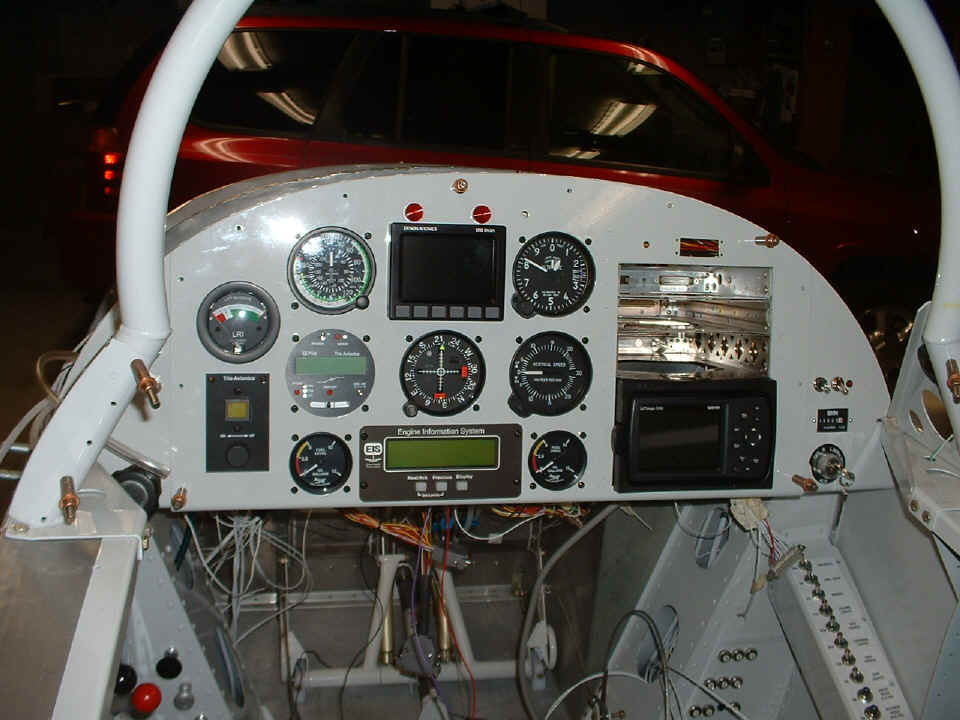
Here is the frontal view of the panel with the forward top skin removed again
for rear panel access. When Wendell re-installed the roll bar to the fuselage, he
put the bolts in the "logical" way instead of the way Van's said to do it.
If you look at the bottom left corner of the photo, you will see a bolt head
holding the roll bar to the fuselage. The nut and washer on the bottom of that bolt
prevent access to the other side of the skin rivets that must be installed with the
forward top skin. With the bolts sticking UP from below, there is clearance for the
bucking bar when riveting the top skin to the fuselage.
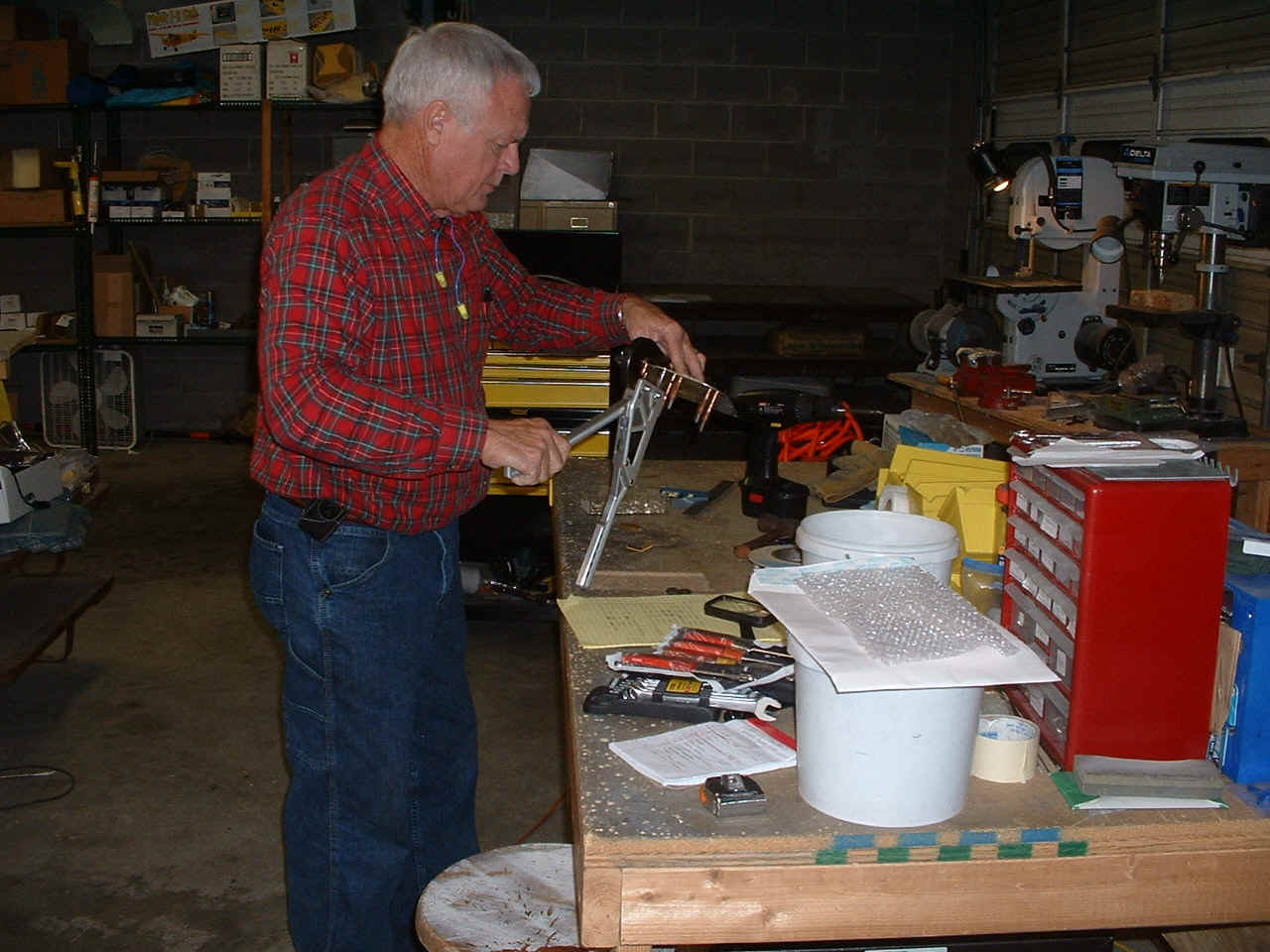
I showed Wendell how to install the lift reserve indicator probe to one of the
wing access panels. He is squeezing the rivets to put the LRI mount to the access
panel that is part of Van's RV-8 wing kit. We had just finished marking the two air
lines that will connect the wing-mounted LRI probe to their gauge on the instrument panel.
That was when I realized it was time to mount the assembly and probe to the wing
access plate.
After the above photo was taken, the instrument panel was removed and placed on blocks on the work table with the front side down on a towel. The purpose for that was to add all the wiring to the indicator lights and make the power connections from each device to the mating DBM-25 connectors to allow easy separation of the instrument panel from the airplane for maintenance issues in the future.
January 16, 2007: The
Tuesday evening session was about getting the strobe cables connected from the power
supply. I made up two short cables to get out of the fuselage to the wing
intersection area. I also added a connector to the cable that runs to the rudder for
the tail light strobe. Here is where they all come together at the strobe power
supply.
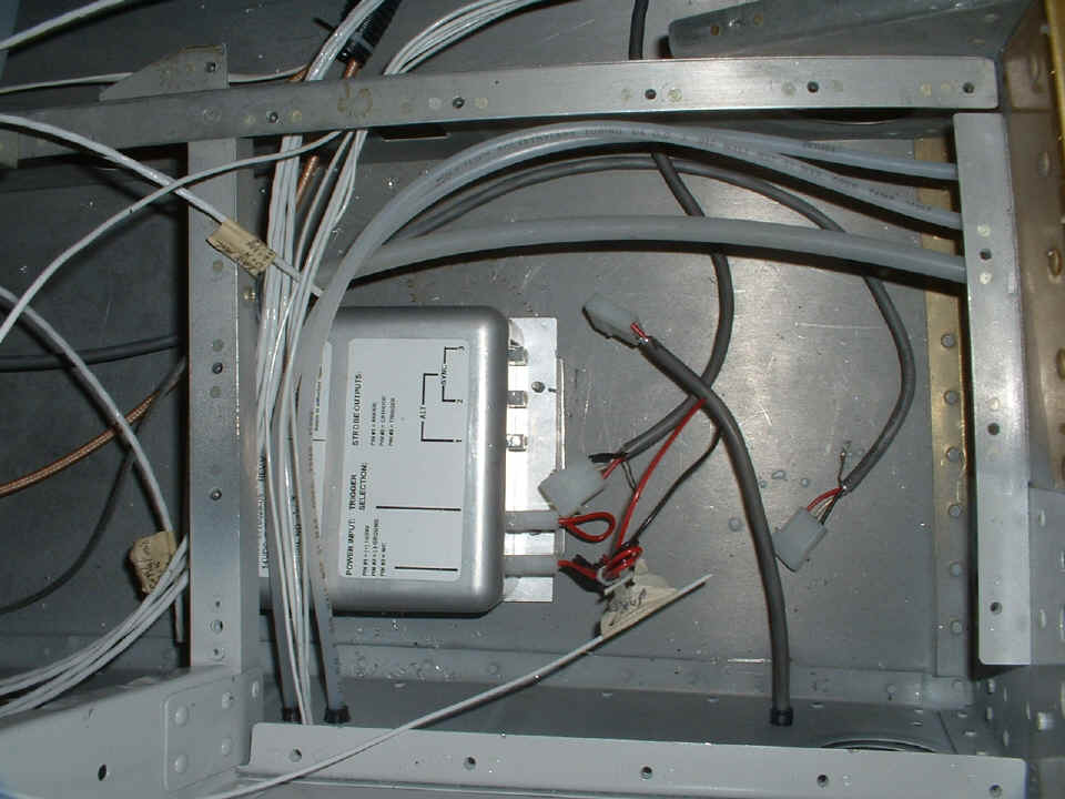
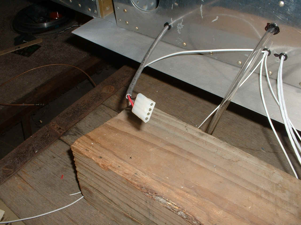
This is one of the connectors at the left wing root location. This 4-pin
connector also connects the shield wire from the gray cable. Notice how the strobe
power cable is separated from the other low-voltage wiring to minimize the chance of radio
and audio system interference. While I was doing the crimping and soldering of the
strobe cables, Wendell was routing the coaxial cables for the NAV, COM, and radar
transponder antennas.
Wendell also thought of a way to mount the ELT transmitter on the back side of the rear-most baggage bulkhead. That will require some metal fabrication and bracing on the removable bulkhead.
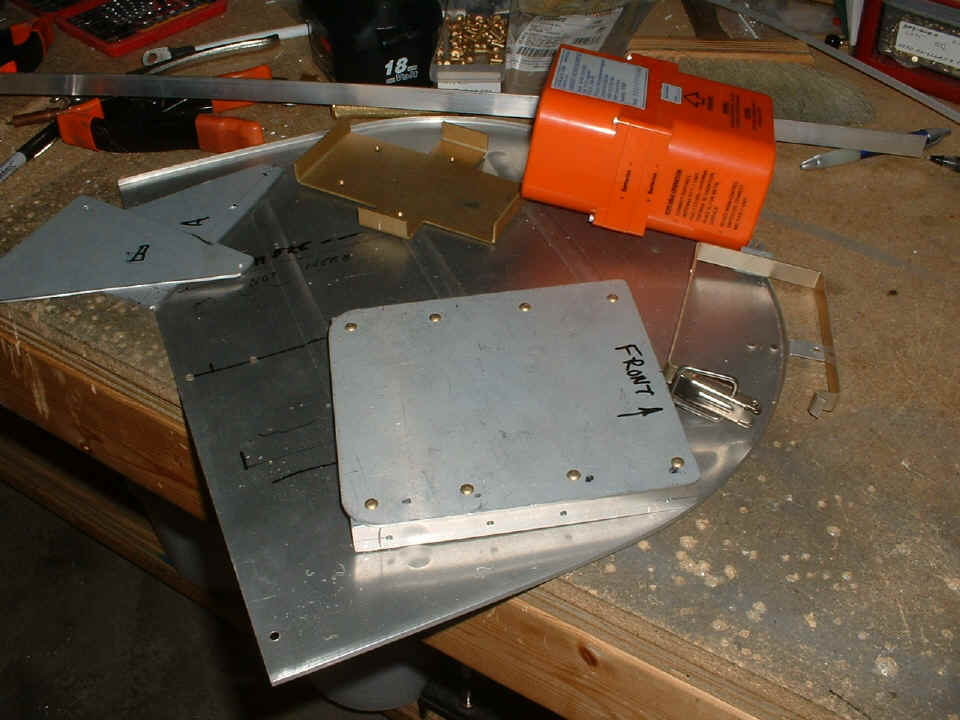
January 24, 2007:
Another evening session with Wendell to get his ELT ready to mount. He decided on
the back side of the rear baggage bulkhead panel. Here are the components ready for
riveting to the panel.
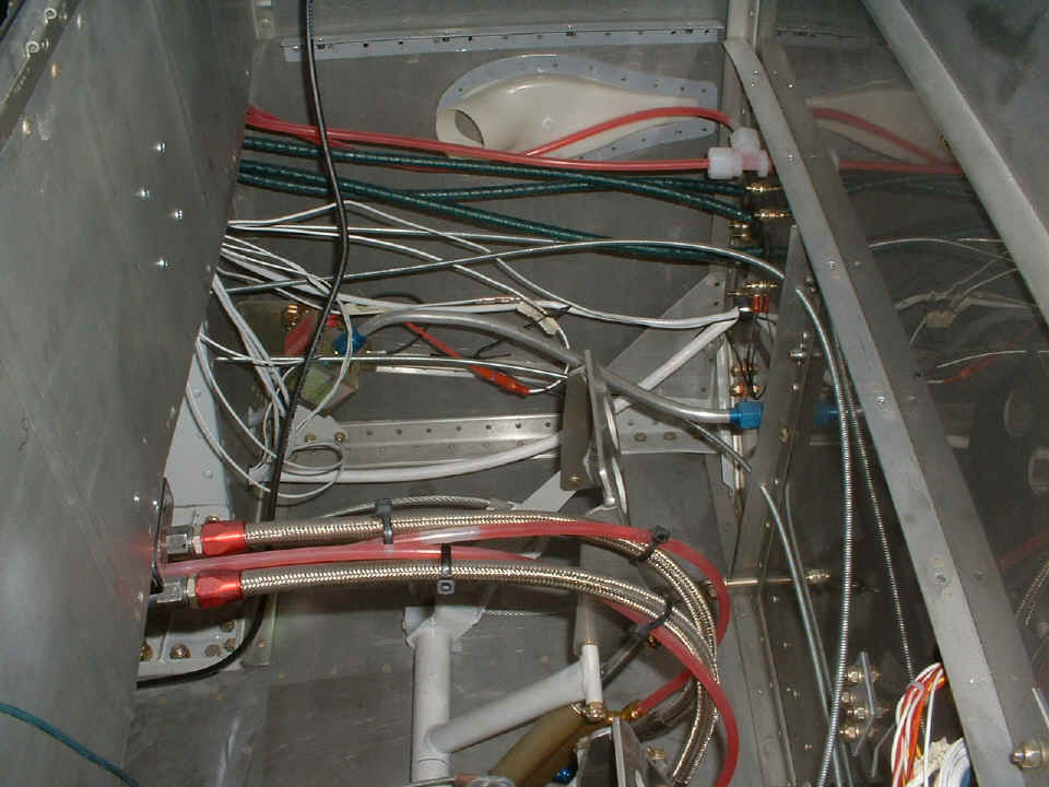
While I was away in California, Wendell has pumped up the brake system with
brake fluid as evidenced by the pink color of the fluid supply lines from the brake fluid
reservoir to the master cylinders down on the rudder pedals. The air bubbles in the
supply lines are not an issue. The lines going from the master cylinders to the
brake cylinders on the wheels are rock solid when you press on the pedals.
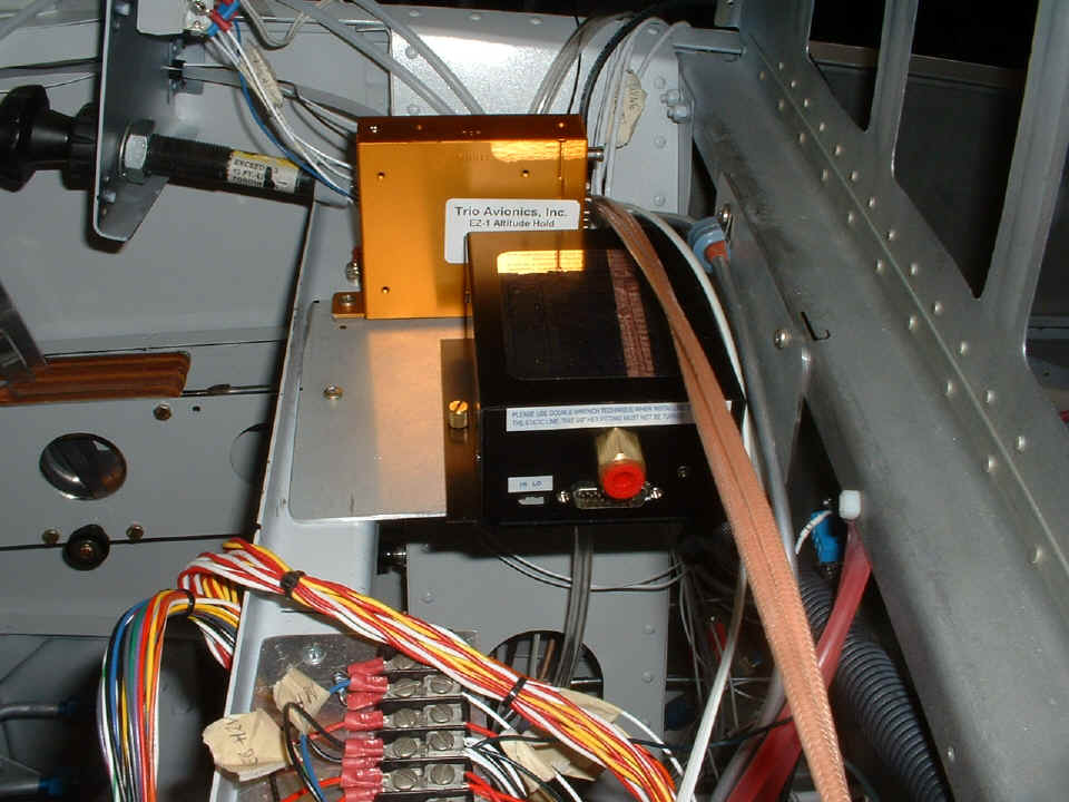
Wendell also made a new mounting plate that now includes the altitude encoder
adjacent to the Trio Avionics altitude-hold control module behind the instrument panel.
| CLICK for Folks PAGE 41 | Return to Other RV Menu | Return to Main Menu Page. |