Wendell Folks RV-8 Project - Page 35.
December 19, 2006: The project goes forward
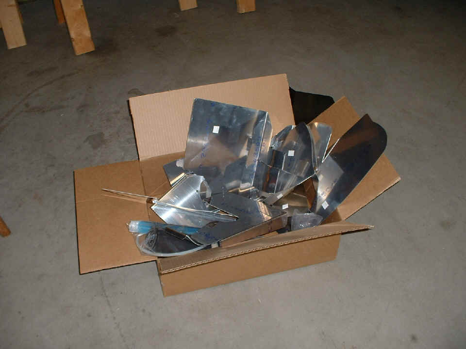
again. Tonight the focus is on the engine cooling baffles. Everything was
unpacked and identified using the enclosed instructions and the parts in hand. I
held each of the pieces up on the engine in the places where each will be attached.
This made it easy for Wendell to get the idea of how all the pieces will eventually come
together. I also took of the upper cowl on my RV-9A to show him the finished
product. The baffle kits are very similar for my O-320 and the O-360 that Wendell
has on his RV-8.
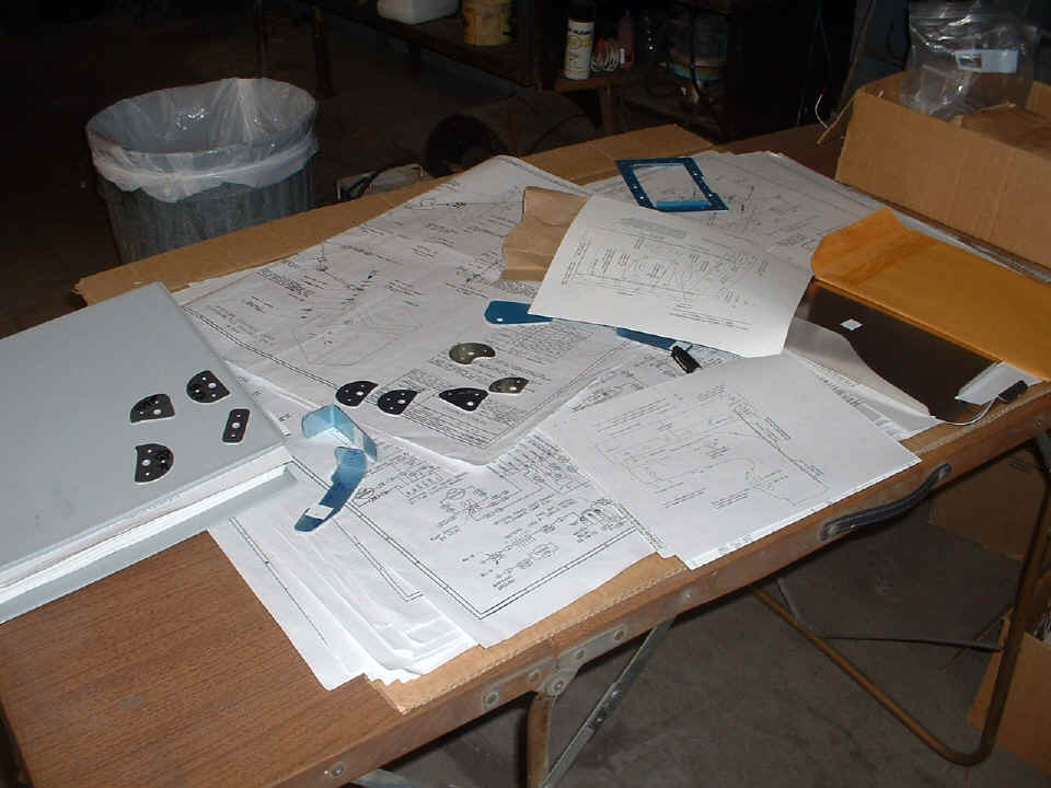
The various doublers are laid out on the table with the baffle plans and
instructions. Each part was labeled with a Sharpie marking pen and matched to the
larger parts of the baffle kit.
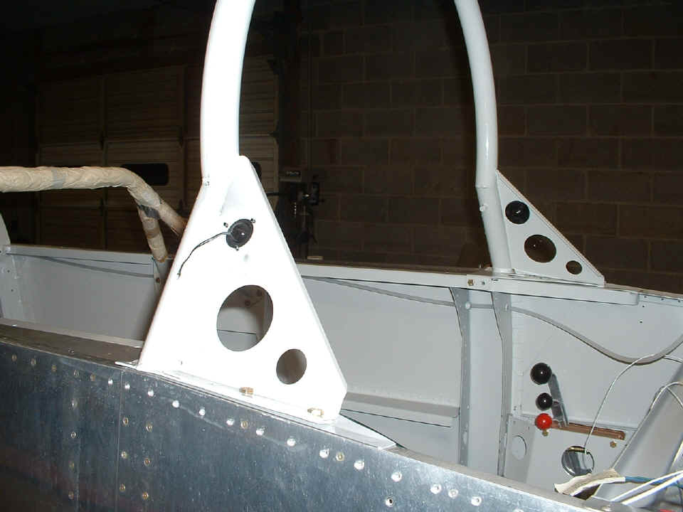
The roll bar now has two eyeball lights attached. The mounting screws
have been cut short with a Dremel tool. This will ensure clearance from the forward
top skin when it gets installed. The wiring is moving along as each new part is
installed. I marked the blue and green wires from Lasar ignition controller.
These are the "P-Lead" wires that turn the mags on and off during engine run-up
testing. We will be putting in the instrument panel and connecting wires to it
soon. All of that wiring has to be completed before the forward top skin can be
installed.
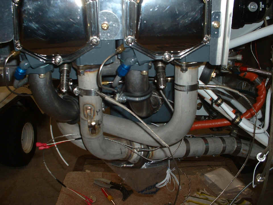
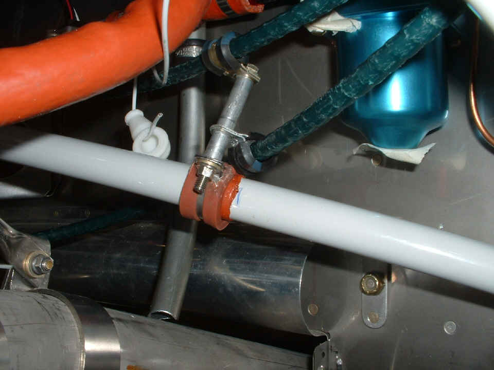
I marked all four locations for the exhaust gas temperture (EGT) probes. Wendell will drill those holes in the exhaust header pipes. He also finished up the routing and securing of the three engine control cables for throttle, mixture, and propeller governor. I forgot to take any pictures of the clamps that route the cables tonight. I will get those photos next time.
December 21, 2006: I
have just returned from Wendell's work shop after providing some additional guidance to
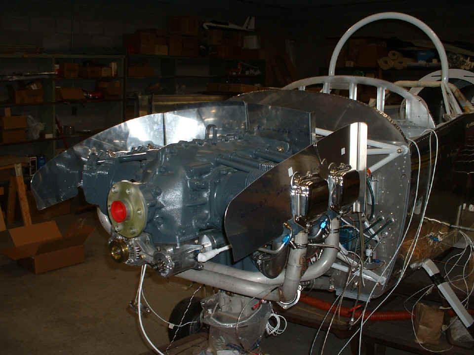
the engine cooling baffle assembly on his RV-8 and the O-360 engine. I removed the
bottom cowl from my RV-9A to reveal the underside methods of attaching the baffles.
For now, the fit is about getting the sides and back pieces on and attaching the doublers
at the bolt locations. I also showed him how to cut out the clearance slot to the
stainless steel oil line going to the propeller from the prop governor.
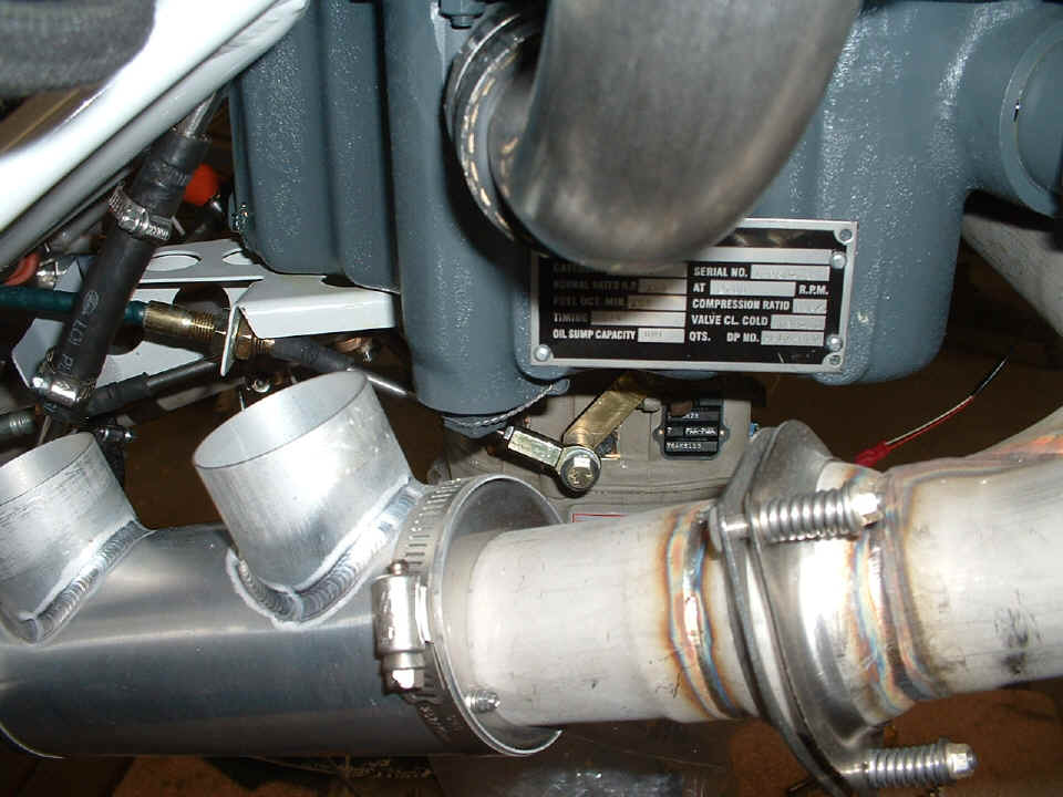
The EGT probes are drilled and attached. We had to remove one of them on
the number 1 cylinder to insure it would not be damaged while working on the front baffle
on the RIGHT side. That is the one with the slot cut in it to clear the oil line
going to the propeller hub.
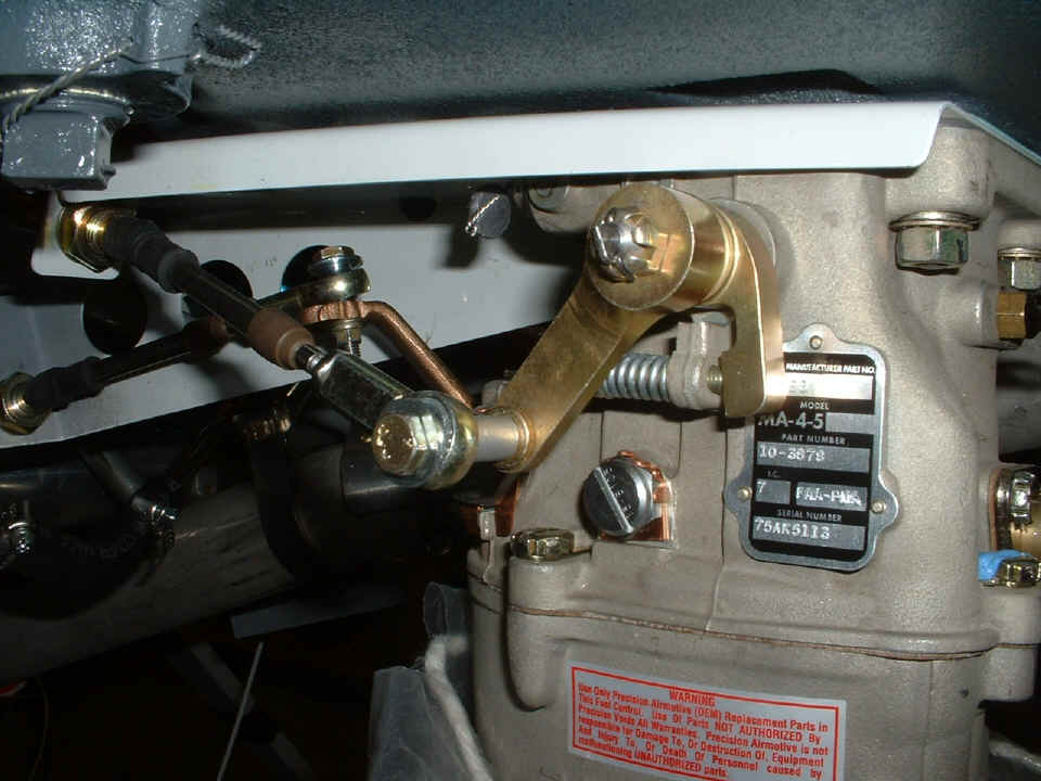
Here is a view of the throttle control linkage to the carburetor from the side.
Here is another closer look that includes the mixture connection. I just
noticed that he may be missing a small washer between the rod end bearing and the mixture
arm on the carburetor. I will have to make a closer inspection in our next session.
Between the firewall and the carburetor, those control cables going to the
carburetor had to be secured with some ansel clamps and standoffs. There are still
some loose wires that have not been routed to their destination and terminated. The
screws on the gascolator have to get safety wire before we are finished in this area.
There will be a drain pipe and valve attached to the bottom the bowl for easy
access below the cowl.
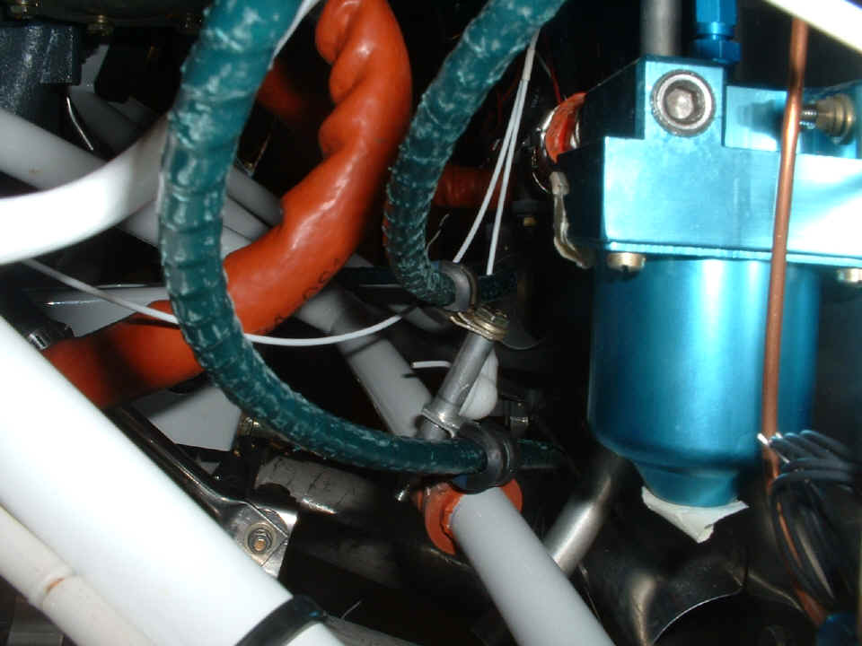
Here is another view of that same clamp and spacer arrangement holding the
throttle and mixture cables enroute to the carburetor. The tape on the bottom of the
gascolator is to prevent possible insect ingress and habitation during construction.
The oil vent tube from the engine crankcase is directly above the LEFT exhaust pipe.
| CLICK for Folks PAGE 36 | Return to Other RV Menu | Return to Main Menu Page. |