Wendell Folks RV-8 Project - Page 27.
September 9, 2006: Saturday and another
afternoon/evening session with Wendell gets us closer to the mounting of the engine.
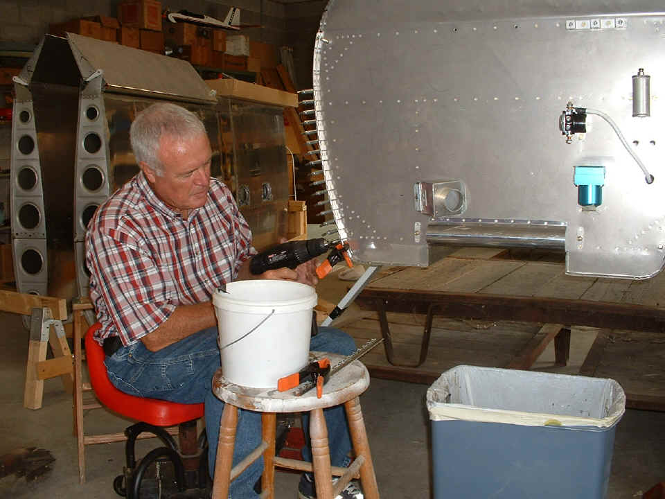
To say Wendell is getting excited is an understatement. This the second of
the four hinges for mounting the lower cowl being drilled and prepared for riveting.
The cabin heat vent door is loosely bolted in place for now. Wendell got a
better-sized knockout punch to make the hole behind the cabin heat door assembly.
The first tool he had was 3/8" over-sized. The tool used today was only
1/16" under-sized.
We made sure the hinges could be riveted easily before the engine mount was
bolted on to the firewall. We also checked the thickness and fit of the lower cowl
to determine if shims were needed between the hinges, the firewall, and outer skin.
Those shims can be added when it is time to finally rivet the hinges in place. Look
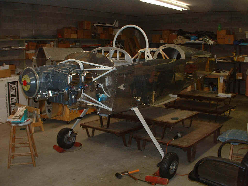
at the bottom left corner of the photo. There are three warehouse jack pallets
stacked under the fuselage to provide a platform and steps to get to the cockpit area.
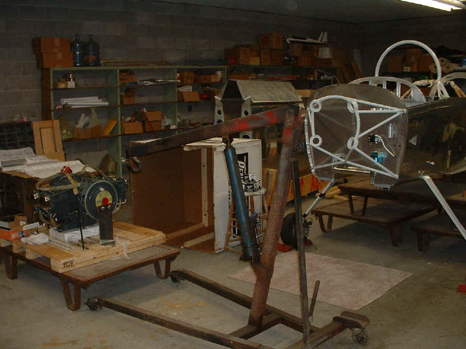
The engine has been moved to the other side of the shop. This provided a
chance to inventory all the items to be installed before the engine is hung on the mount.
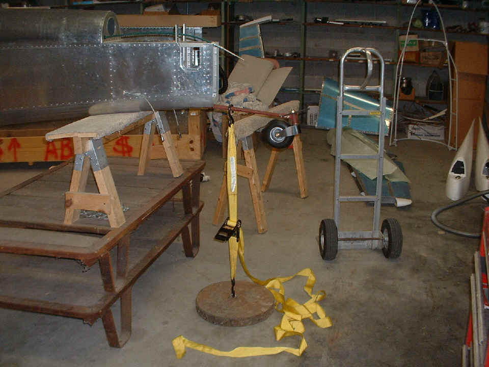
The last photo before we called it a night shows the heavy steel weight hooked
to the tail wheel assembly of the fuselage. This will prevent the airplane from
falling on its nose when the engine is bolted into position.
September 11, 2006: We
will never forget the TWIN TOWERS. This was the evening
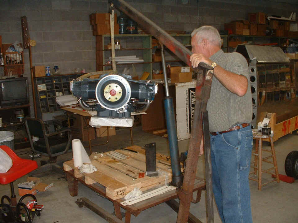
session when Wendell got to put the engine on the fuselage. The session began with
the two large blue AN-fittings installed on the engine accessory case to route oil to the
oil cooler and back. The prop governor was installed along with the oil temperature
sensor on the right-angle oil filter adapter. Then it was time to lift the engine
and roll it into alignment with the engine mount. At that point, the dance with the
engine mounts and bolts began until all four bolts were secured.
After a few tries all four bolts and the rubber engine mounts all found their
proper places. After that, we got out the LASAR ignition control module and checked
out its possible mounting locations on the firewall. We had to provide the clearance
needed for the prop governor and its control cable, the tachometer sensor, oil pressure
sensor hose, etc.
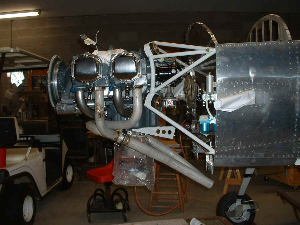
The big surprise of the evening came when we tried to re-install the oil filter
and discovered the right-angle oil filter adapter was too short to get past the engine
mount. This is the same right angle adapter that is on my 0-320 and my RV-9A.
The problem is the angle of the support tubing from the upper longeron attach point to the
back side of the ring of the engine mount. The wider fuselage of the RV-9A provides
a different angle for the steel tubes that interfere with the oil filter on the RV-8
mount. This photo shows that a right-angle oil filter about 1-inch or 1.5 inches
longer would clear the engine mount steel tube. The other alternative would be a
straight adapter instead of the 90-degree adapter shown here.
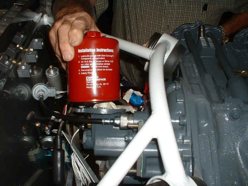
The masking tape in the photo above is temporary to keep bugs from trying to nest
in the open ports. We also were looking at the possible locations for the tachometer
sensor on the firewall. In this photo, it is shown pushed out of the way on the LEFT
side of the firewall. The tach sensor will probably end up on the RIGHT side of the
firewall.
September 12, 2006: Wendell ordered the oil filter adapter extension kit from Penn Yan Aero today. The kit will ship directly from ECI in San Antonio, Texas. When it arrives, it will resolve the oil filter clearance issue in the photo above. He also finished the installation of the aluminum tube fuel lines from the fuel selector valve to the exit ports in the fuselage at the wing root. You can see the fuel line sticking out on the right side of the next two photos below.
I had another evening session with Wendell to get him further along on the engine accessories, etc. Three friends were there for parts of the session. While Wendell was working under my supervision, I found myself explaining the various connections of tubing, hoses, and wires to his friends. The carburetor went on first. Later we discovered it would have to come off again due to a engine mount interference fit problem with Van's bracket that secures the front end of the throttle and mixture control cables going to the carburetor. More about that in a later session.
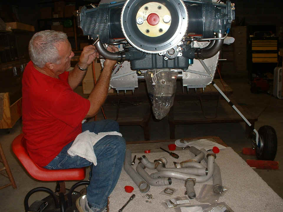
I made sure Wendell installed the screw-in bayonet fitting for each of the four
cylinder head temperature (CHT) probes on the bottom side of the cylinder heads. In
this photo, Wendell is putting on the first of the header pipes on cylinder number three.
The remainder of the Vetterman exhaust system is visible on the carpet below the
engine.
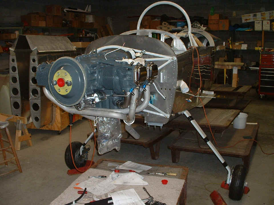
The photo below shows all the header and exhaust pipes installed, but none of
the supporting links are installed yet. I reviewed the sketch showing the placement
of those supports, but also assured Wendell that I would remove the cowl from my airplane
before I leave on my business trip in my car. With the cowl off my engine, he will
be able to see the things that are similar on the two airplanes as far as exhaust
mounting, fuel lines, control cables, etc.
I reviewed the next steps Wendell will be doing while I am away on business
next week. It was a review of the various hoses and fittings that can be installed
to the fuel and oil pressure sensor manifold mounted on the firewall. I also
explained the fuel flow routing from the gascolator through the fuel flow sensor and to
the engine-driven fuel pump. He will need short custom-build fuel line with fire
sleeve installed on it to connect the gascolator to the fuel flow sensor. We
fine-tuned the mounting location for the Lasar ignition controller module on the firewall.
Here is another view of things when we stopped work on the engine.
| CLICK for Folks PAGE 28 | Return to Other RV Menu | Return to Main Menu Page. |