Wendell Folks RV-8 Project - Page 15.
March 11, 2006: The only days that Wendell and I can get together are Saturdays. My new day job keeps me on the road or in my office working online or on the phone with customers. The weather today was warm, windy, and threatening - - a good day to work on airplanes instead of trying to fly them in bumpy conditions.
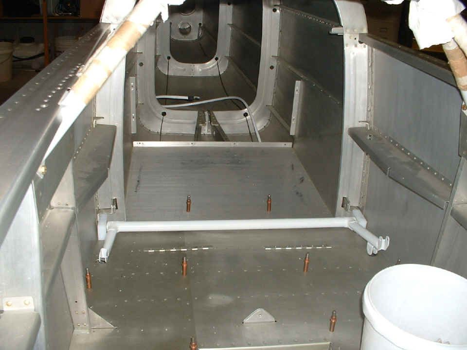
I took this picture when I went to visit Wendell's shop on March 6th. He
was starting to work on the flap actuator linkage and baggage floors. The UHMW
plastic blocks at the ends of the steel flap actuator arms required some trimming to fit
in the cramped space behind the passenger seat location.
I had previously given him some guidance on getting the switch/breaker console
installed on the right side of the cockpit.
The front baggage floor has been fitted and all platenuts are installed to
secure it when the time is right. For now, it rests in here until it is time to work
in the rudder pedal area again down below this shelf.
The next photos were taken during my visit on Saturday, March 11, 2006.
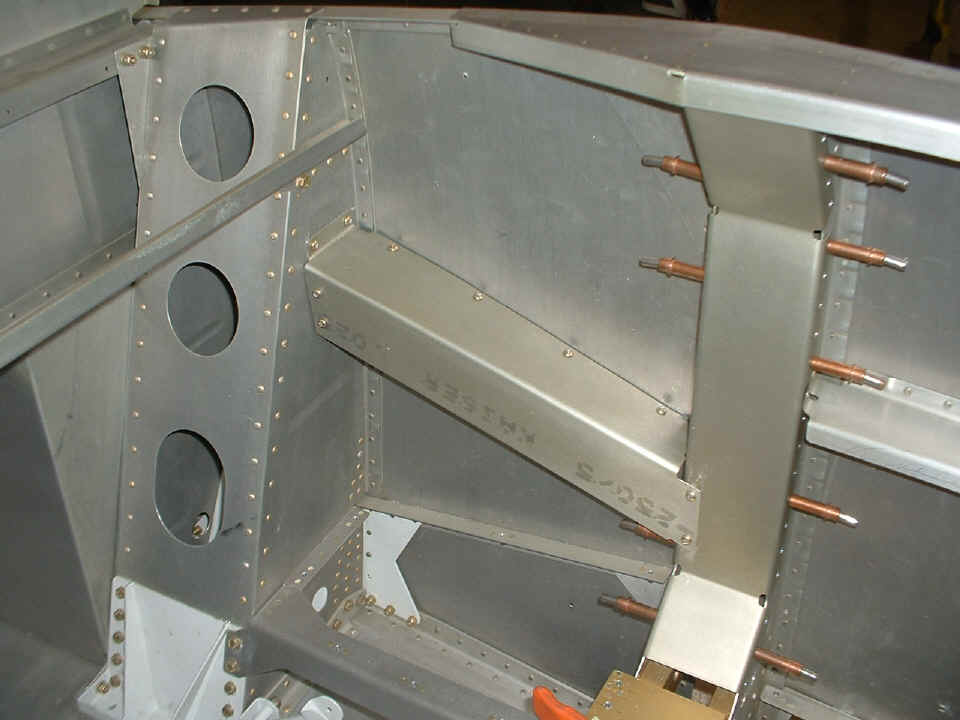
Wendell is removing the flap actuator weldment before removing the seat bottom
panels/floor to work in that area. The flap motor had previously been fitted to the
linkage and the holes drilled in the seat back bulkhead to secure the upper end of the
flap motor.
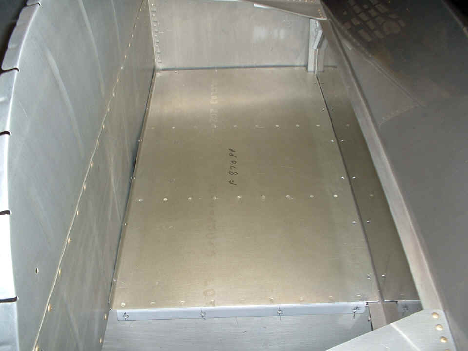
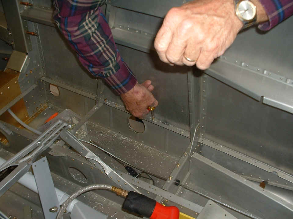
Wendell has received his strobe lights and power supply for them. This is
the floor area on the right side of the airplane where he is installing more plate nuts
and converting part of the floor to be removable. The hole in the fuselage under his
hand is for the fresh air port for the rear seat. The strobe power supply will also
be mounted in this area below the floor panel.
With less and less to do down on the floor level, we have started to consider
the instrument panel and how it is fitted to the fuselage sides and the forward top skin
of the airplane. Here it is clecoed together on the work table for the first time.

We reviewed the plans and instruction manual to determine how much additional structural work remains to be done before we can start wiring and putting in throttle quadrant control cables, landing gear legs, forward top skin, etc. At this point, I could appreciate my RV-9A manual much more than the earlier format of the RV-8/8A manual. The fuselage will be rolled over soon to do the work on the landing gear leg attachments, alignment with the each other, and to be perpendicular to the fuselage center line.
| CLICK for Folks PAGE 16 | Return to Other RV Menu | Return to Main Menu Page. |