Wendell Folks RV-8 Project - Page 16.
March 19, 2006: This page was posted on March 26th. I apologize for the delay due to my travels on business, but it is good to be earning a pay check again! I have to have some way to support my flying hobby and helping other RV-builders.
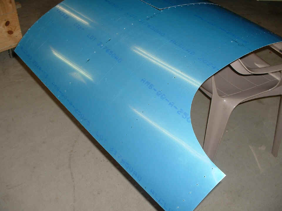
The forward top skin has been trimmed to shape to clear the roll bar and is
ready for fitting to the fuselage.
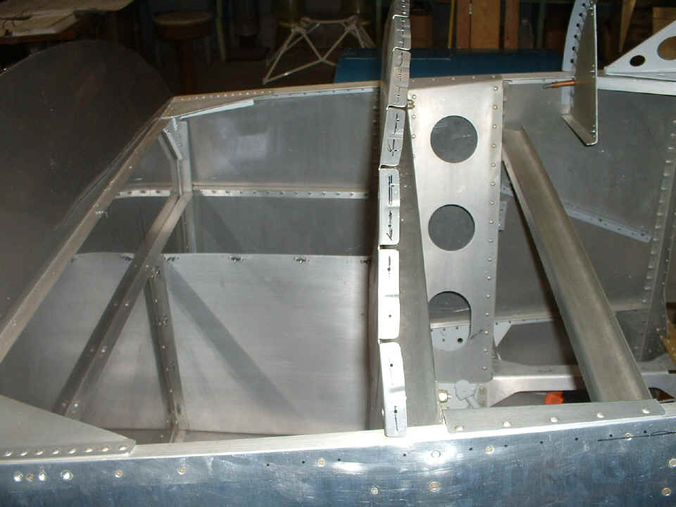
The instrument panel is clecoed in position and the forward bulkheads were
drilled during the first fitting the front top skin to the quick-build fuselage. The
flanges have been fluted between the rivet holes to keep the tabs straight under the top
skin.
The temporary initial fit of the forward top skin allowed the alignment of the
roll bar that supports the windshield and mates to the sliding canopy. Only one bolt
was installed on each side to lock the steel weldment in place before drilling and
installing all the other bolts. My job with Wendell is to explain how the CNC
punched parts are used to align all the key components during the assembly of the
airplane. Once the alignment and fit of the components is evident, the procedures
and proper sequence of that assembly becomes self-evident. I say this since I can
see the differences in the instruction manuals from the RV-8 to the RV-9 manuals in my
project. It is as if Van's Aircraft had improved the manual content since the
development of the RV-9 came after the RV-8 and RV-7.
The whole process of fitting the skin to the forward fuselage bulkheads and the
firewall was based on finding the centerlines of the firewall and the instrument panel and
putting the centerline of the forward top skin over those points. But that is not
all the story as you shall learn further down the page. While this initial fitting
of the forward top skin accurately located the fore and aft position for the roll bar,
there appeared to be a "twist" in the alignment of the forward top skin when the
overlap of the side skins and longerons was examined. At this point in the assembly
I told Wendell to finish drilling the holes to complete the mounting of the roll bar, and
some guidance on how to deburr the holes at the bulkhead between the firewall and the
instrument panel to get the top skin to move slightly in the direction needed to negate
some of the "twist" we observed. No holes would be drilled in the side
skins and longerons until I return for our next session.
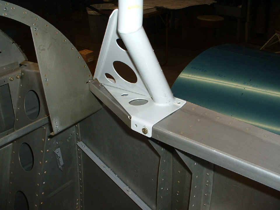
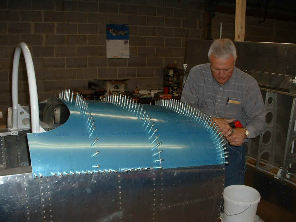
Here is the final fit of the bolts through the WD814 steel roll bar. At
the time I took this photo, only one more bolt remained to be installed. Notice also
that the holes in the bulkhead at the instrument panel have NOT been drilled for skin
attachment. Those won't be drilled until we can more closely align the forward top
skin with the side skins and longerons. The black ink dots on the side skin show how
much mis-alignment occurred during the preliminary fit of the top skin. We have been
working to move the skin closer to the correct position, but more has to be done before
any holes will be drilled in the longerons.

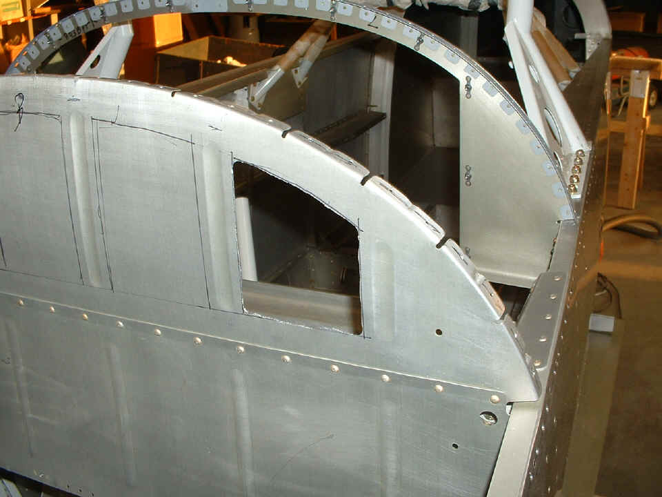
March 25, 2006: I spent Saturday afternoon with Wendell and helped him get the forward top skin in a position suitable for drilling rivet holes for the final assembly of the skin when it is time to do so. The final solution was to extend the existing rivet centerlines across the side skins, then to draw parallel lines on the side skins to show the correct location for the edges of the top skin when it overlaps the side skins. This proved to be a better idea than matching the centerlines of the skins to the instrument panel and its bulkhead.
The width of the firewall flange tabs were guiding factor in the original
alignment of the top skin up front. The location of the holes in the top skin and
their positions over the firewall tabs were the key factor in keeping the rivets in the
correct positions. I will have to add a photo showing examples of this in a later
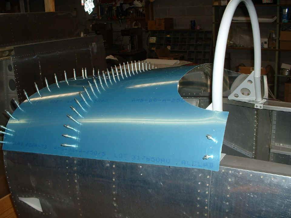
work session. For now, here is the milestone photo showing the clecoes in the top
skin after all the #40 holes were drilled in the side skins and longerons. We have
already removed some of the quick-build rivets and back drilled the top skin through those
rivet holes.
At the end of today's session, I reviewed the baggage door assembly and its components to provide Wendell some things to work on during my work week when I will be unable to guide him in his work on the airplane. He had made a preliminary cardboard layout of his proposed instrument panel configuration of instruments and radios. It will have a new look by the time he gets back from Sun-N-Fun in Lakeland, Florida next month.
April 3. 2006: Here are
a couple of photos of the work that Wendell has been doing on his project during the past
week. The idea here is to make easy access to the area behind the instrument panel
via the forward baggage compartment. I showed him how to use the unibit to make
smooth holes at the corners of the panel area to be removed. After that the hand
nibbler connects the holes, then the files come out to smooth the edges before a final
polishing with a Scotchbrite pad.
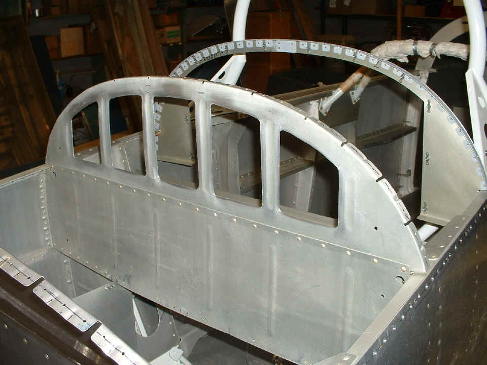
Here is the finished panel after all openings are deburred and polished.
A hinge will be riveted in place above the row of round-head rivets below the
openings. The door panel that will be hinged there will swing up against this
bulkhead to close off access to the rear of the radio stack and instrument panel.
There is also a stiffener brace that goes from the top center of this bulkhead to the top
center of the firewall. The baggage door hinge is riveted to the top of that
stiffener and the forward top skin.
He has also been working with a cardboard mockup of the instrument panel to start thinking about where he wants all the goodies placed. Upon advice from another RV-8 builder, the baggage door work will wait until the engine and cowling are installed. For now the spacer in the forward top skin will remain in place for proper alignment of the cowl.
We should be turning the fuselage over to work on the gear leg alignment and installation after he returns from Sun-N-Fun in Lakeland, Florida.
| CLICK for Folks PAGE 17 | Return to Other RV Menu | Return to Main Menu Page. |