Wendell Folks RV-8 Project - Page 12.
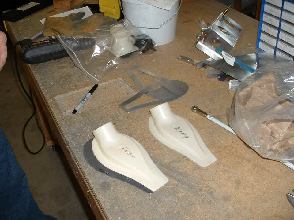
January 10, 2006: Here are a couple of
photos of the work being done before the fresh air scoops are ready to be installed.
Wendell had read the instructions and used the outside air access template to cut
these doubler plates. I pointed out that those templates were drawn in the days
before the prepunched series of kits from Van's Aircraft. The access holes are
already present in the side of the fuselage and under the wing for the RV-8. The
ports are also pre-punched in the fuselage sides of the RV-7/9. I had to point to
one tiny section of a drawing in the air scoop instructions that called for a doubler
plate on the back side of the plastic scoops to get my point across about how the doubler
plates should be made.
After some work with the tin snips, and some frustration with my scroll saw,
the doublers began to take shape as the afternoon progressed for Wendell. I went
next door to clean my airplane after the return trip from Florida yesterday.
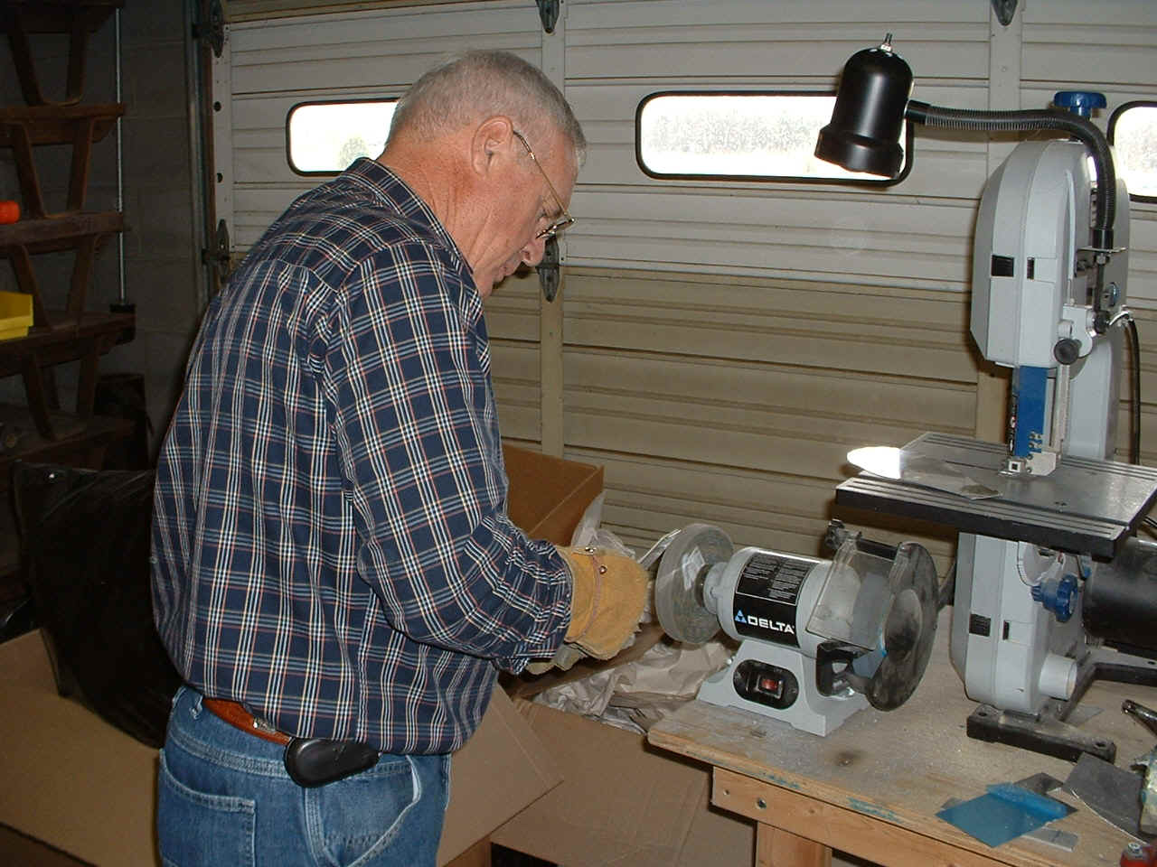
By the end of the work day, the doublers for both air scoops were ready to match drill to the scoops. It took a lot of filing and work with the deburring tool, but they finally became the parts we wanted to match the plastic air scoops.
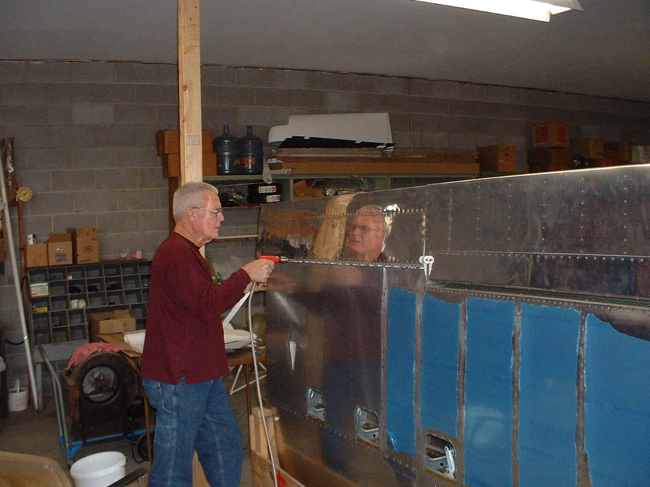
January 11, 2006: Both air scoops got the
rivet holes drilled in them and the aluminum doublers that go behind them. The air
scoop for the rear seat passenger was installed on the right wing along with the scat tube
to connect inside the wing. The other thing done today was to get the RIGHT wing off
the wing jig, and then to put the flap on the RIGHT wing while it is sitting in the wing
cradle. After the new flap hinge was match-drilled to the lower wing skin of the
right wing, the flap was removed, the hinge pin was pulled, and the newly drilled hinge
was clecoed to the edge of the work table. I then demonstrated to Wendell the
correct way to set the depth on the countersink tool and made ONE hole fit the dimple
template that simulates the lower wing skin thickness. He gets to finish
countersinking the remaining holes in the hinge that will be riveted to the wing when it
is primed with all the other parts that are in progress.
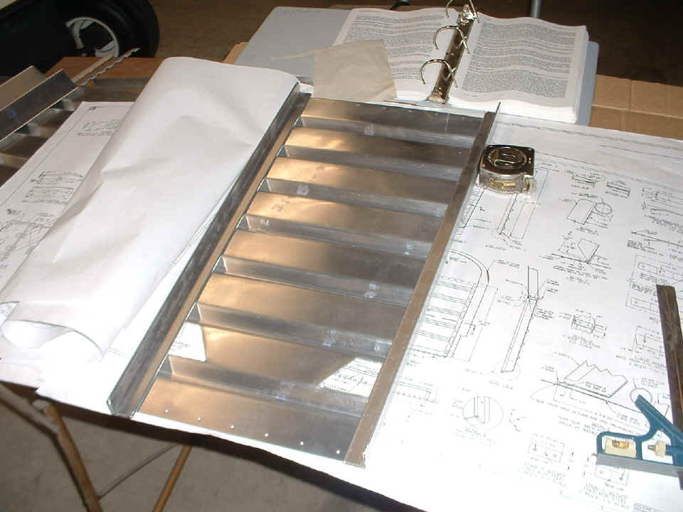
January 12, 2006:
Wendell went to work on the flap hinge this morning. I had to share a little secret
about how to get the depth of the countersink properly when using a hand drill instead of
a drill press. That triangle-shaped piece of aluminum scrap has a sample dimple that
is used to confirm that each countersink has been done properly. After this work
table task was completed, the hinge was put back on the right wing and the lower inboard
wing skin was dimpled to match the countersinked holes in the hinge flange.
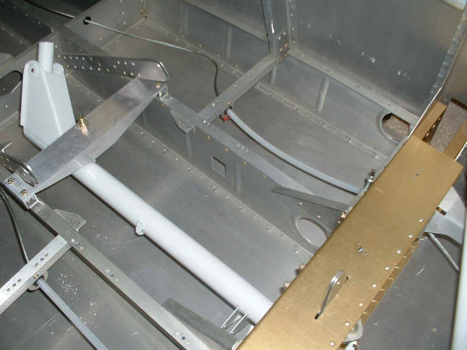
The fuselage got more work after the wing flap hinge was put away for later
priming. If you look at the plastic tube over the rudder cable in the lower left
corner of the picture, you will see the red tail of a tie-wrap securing the tubing to the
bracket and bushing that keep it from sliding back and forth when the rudder cable is
moved. The tubing prevents metal-to-metal contact of the rudder cables and the foot
wells for the rear seat passenger. We had the foot wells and the front seat bottom
plate clecoed together and in position to drill the screw holes for the entire assembly.
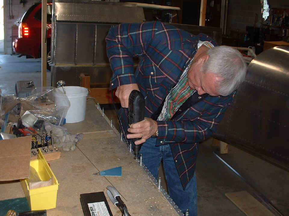
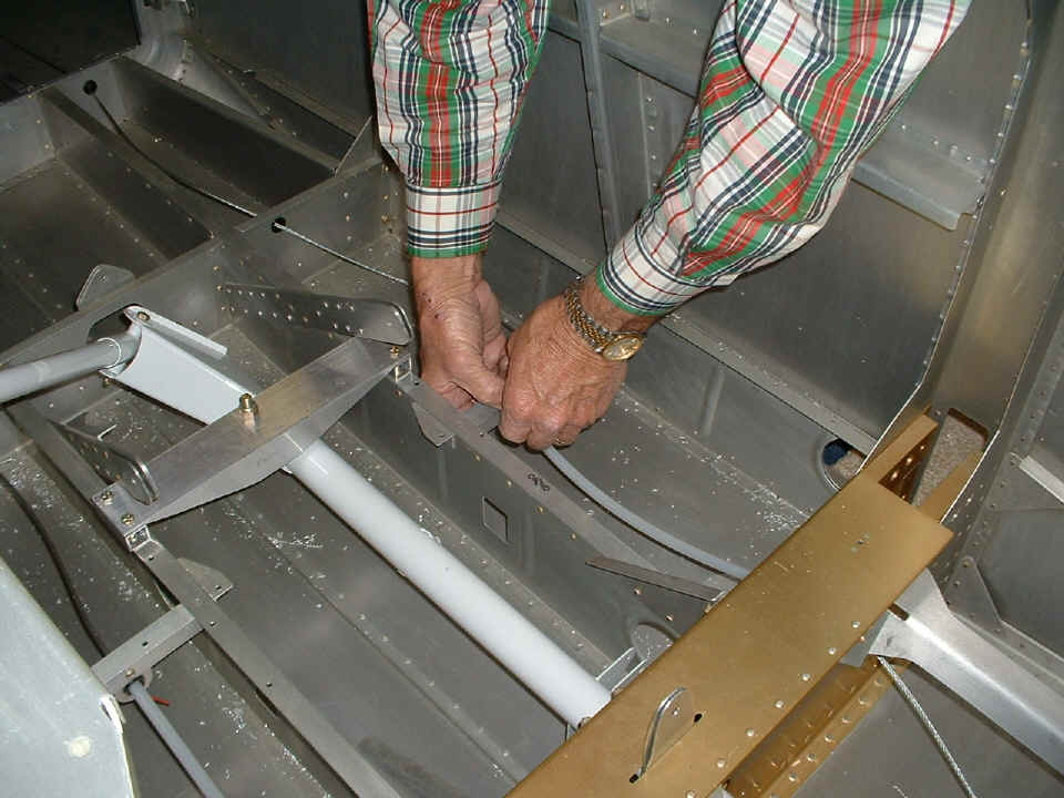
What you see happening below is preparations for drilling rivet holes for the
platenuts used to secure the front seat bottom panel and the foot wells. The
procedure is simple, put the screw up from the bottom side of the support angles with the
plate nuts on the top side. The rivet holes through the plate nuts are drilled next
by clamping the nut plate in the correct position, drilling one rivet hole, then putting a
cleco in that hole before removing the clamp and drilling the second hole through the
other rivet hole in the plate nut.
At about 4 PM, we stopped work for the day and flew off in Wendell's Aeronca Champ to go visit another RV-8 builder about 44 miles down the valley at his grass strip near Cedar Bluff, Alabama. You can see some photos I took there in the OTHER RV section of this web site and get a first set of photos of John Myers and his RV-8 project.
January 13, 2006: Wendell finished up much
of the work on the front floor cover plate nuts riveting them in place. At the end
of that work, the vacuum cleaner came out to get rid of many aluminum filings from
drilling all those holes.
The pilot seat also got the tabs nibbled out and deburred on the edges to allow
passage of the pilot seat belts through the seat back. The two side rails for the
pilot seat were cut, but not yet finished.
| CLICK for Folks PAGE 13 | Return to Other RV Menu | Return to Main Menu Page. |