Wendell Folks RV-8 Project - Page 6.
November 4, 2005: The left elevator new skin
was installed on the skeleton, then the leading edge was rolled and blind-riveted.
This was the first time the left elevator had the rod-end bearings installed and was
bolted to the left side of the horizontal stabilizer. When I saw the skin overlap
with the counterweight arm, I checked the print and found something I had not seen
before. It is obvious there is some aluminum to be trimmed away to allow for
elevator operation. It also changes the cut to be made to the fiberglass tips of the
horizontal stabilizer.
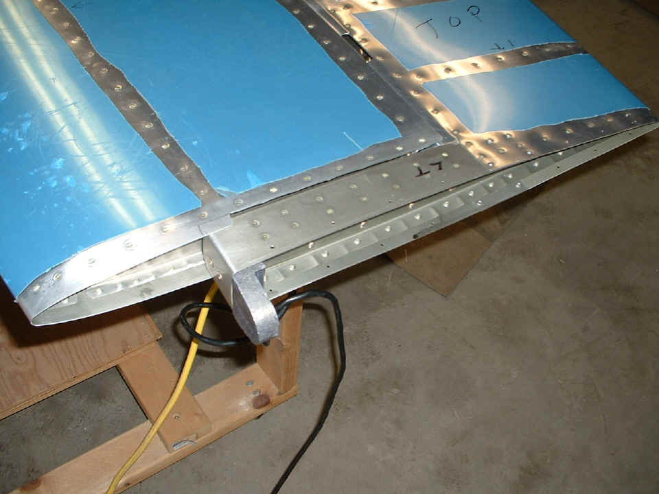
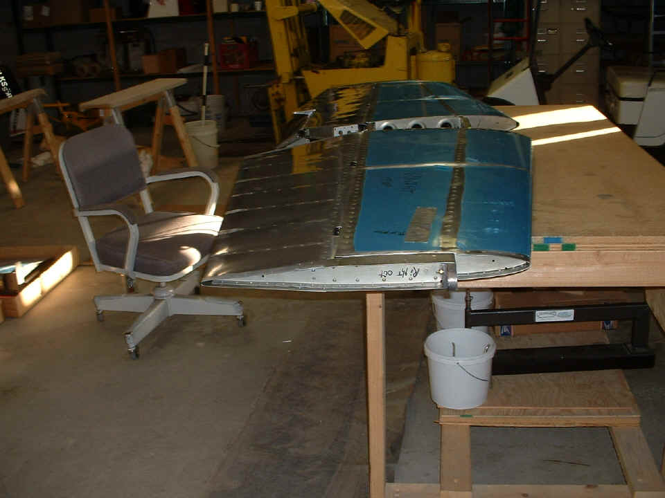
I just had to stand back and take this picture to show these pieces joined for
the first time.
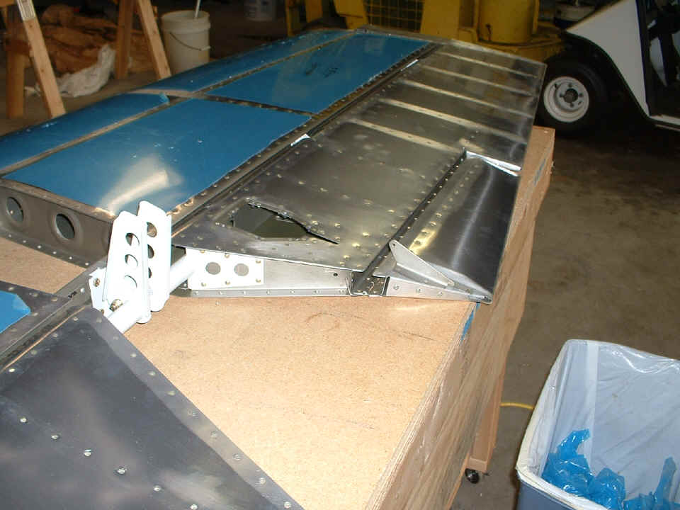
The photo below shows the elevator movement range after the overlapping portion
of the horizontal stabilizer has been cleared from the path of the elevator
counter-balance arm. The leading edge curve of the elevator skin does not rub
against the rear spar of the horizontal stabilizer. That proves the rod-end bearings
are close to their final settings. I had Wendell to remove all the plastic to show
him how close the LEFT elevator and trim tab would come to being balanced on the bolts
that hold it to the horizontal stabilizer. He learned the technique of rolling the
leading edge of the elevator skin today.
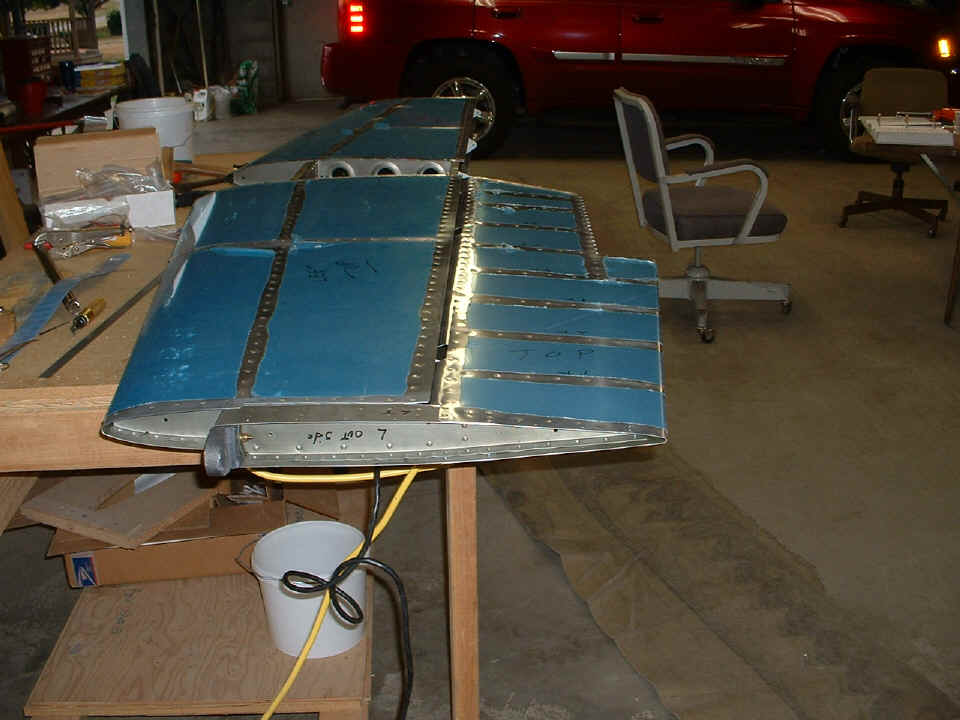
November 5, 2005: I got a call from Wendell late in the afternoon telling me had finished the RIGHT elevator and hung it on the horizontal stabilizer in the manner shown in the photo above. He trimmed the extra aluminum off the right end of the horizontal stabilizer to allow free movement of the elevator. He reported that it was "nose heavy" since there is no trim tab on the right elevator. I reminded him that when BOTH of the elevators are bolted together and tied to the elevator push-rod, the overall balance should still be slightly nose-heavy to offset the weight of the paint when it is applied at the finish of the project.
Wendell said he would not being working on the elevators again until I am with him. We want to avoid the mis-drilled torque arms that I had on my elevators. In our next session, the clearance of the center pivot bolt at the center bearing will be confirmed. If any further adjustment of the rod-end bearings is required, it will be done before the torque arms are drilled through the center bearing.
November 7, 2005: Monday
always gets me out to the shop with Wendell to get things going again and to see if he did
any work on the previous Saturday. He had rolled the leading edge of the right
elevator and closed it with blind rivets on Saturday. He also trimmed the excess
aluminum from the right horizontal stabilizer to allow free movement of the elevator
counterbalance arm. My instruction for him today was the correct way to install the
rod end bearings on the elevator spars to secure the elevators to the horizontal
stabilizer halves. It was during that process that I discovered that Wendell had
overlapped the skins the wrong way at the front of the right elevator. When I
pointed out how rain could go down inside the elevator due to the wrong overlap, he wanted
to immediately remove and replace the blind rivets with the skin overlapped properly.
When all these steps were completed, the pivot holes were drilled through the
elevator control horns and they were bolted together.
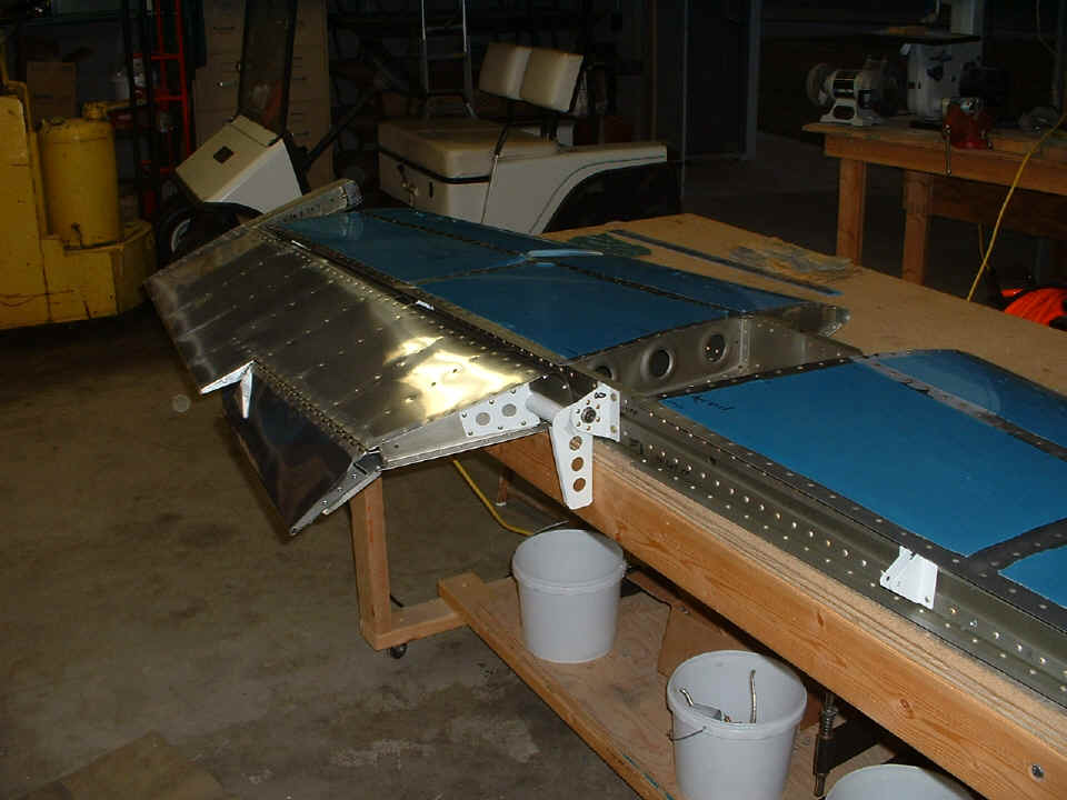
As a pair, the elevators were balanced when they were bolted together at the
center bearing with the appropriate stacks of spacer washers on each side of the center
bearing. Since there is no paint on them at this time, it was obvious that
additional weight will be needed on the counterbalance arms when the elevators are finally
painted. I later showed Wendell how we could install a 3/16" plate nut on each
counterbalance arm using the existing tooling holes for passage of the bolt through the
arms. The purpose was to provide a place on the forward portion of the arms for the
installation of some additional lead weight or washers to balance the elevators after
painting them. The tooling holes are located just to the right of the hand-written
words "right out" in the photo below. Both elevators got a plate nut
riveted in at that location.
After checking the range of motion of the elevators, I got out my hand nibbling
tool and introduced it to Wendell for the first time. It was also the first time he
had seen my angle finder tool. Van's instruction book talked about cutting away a
portion of the lower edges of the aft spar to allow the control arms the clearance needed
for proper elevator movement up and down.
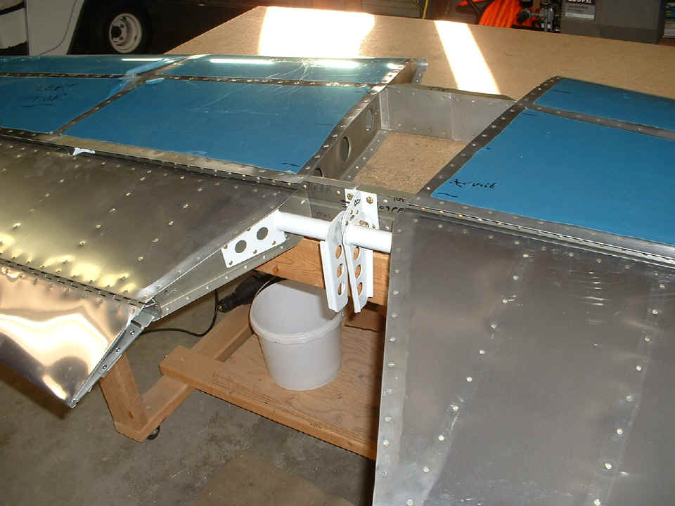
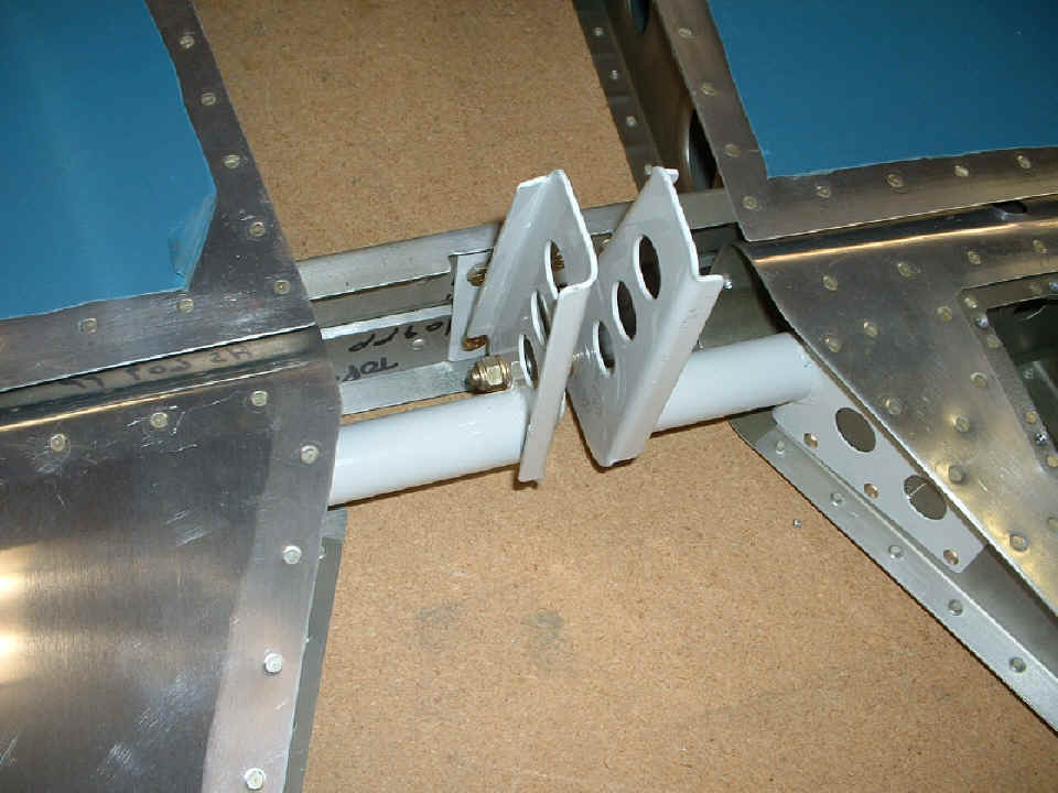
Here is a closeup view of the bolt going through the center bearing and both
elevator control horns. One of the hand-nibbled notches in the aft spar is visible
after Wendell deburred the edges and rounded the corners of the cuts. After the
trouble I had when I drilled these holes at the wrong location, I was not about to allow
Wendell to put his holes in the wrong locations. The head of the bolt and the nut
were both well clear of the round steel tubes of the torque arms.
| CLICK for Folks PAGE 7 | Return to Other RV Menu | Return to Main Menu Page. |