FIREWALL FORWARD - Page 63.
October 28, 2004: This is a symbolic day for
me. Two years ago on this date, I put the first metal parts of the horizontal
stabilizer together to begin this construction project. Today, I removed the
propeller and lower cowl after making a sketch of the dimensions between the number 1 and
2 cylinders and the air scoops of the lower cowl. I am now beginning to fit the
cooling baffles to the engine and will begin to trim them to the proper dimensions in
coming work sessions.
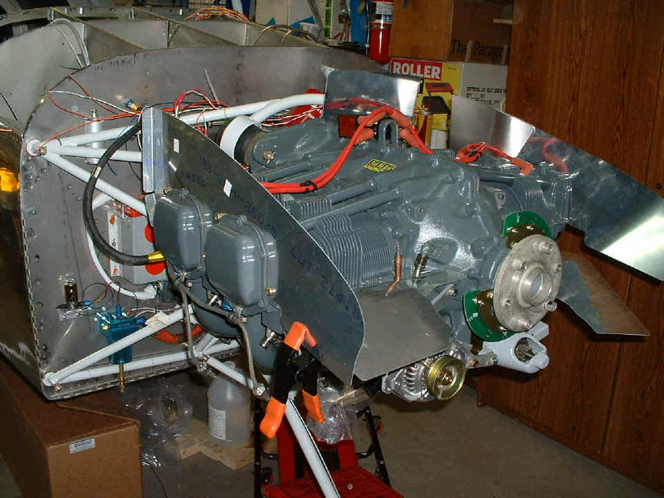
There are now two baffle plates connected on each side of the engine. I
marked them for trimming along the FRONT end of those plates, but the other dimensions
will be cut to clear the upper cowl when the time comes. This jigsaw puzzle will
take some careful reading of the prints and measurements on the engine and the lower cowl
to get it all done correctly.
October 31, 2004: I went flying yesterday
morning and that is documented HERE. I put in 1.4 hours
on the airplane project yesterday evening and began modifying some of the baffles for a
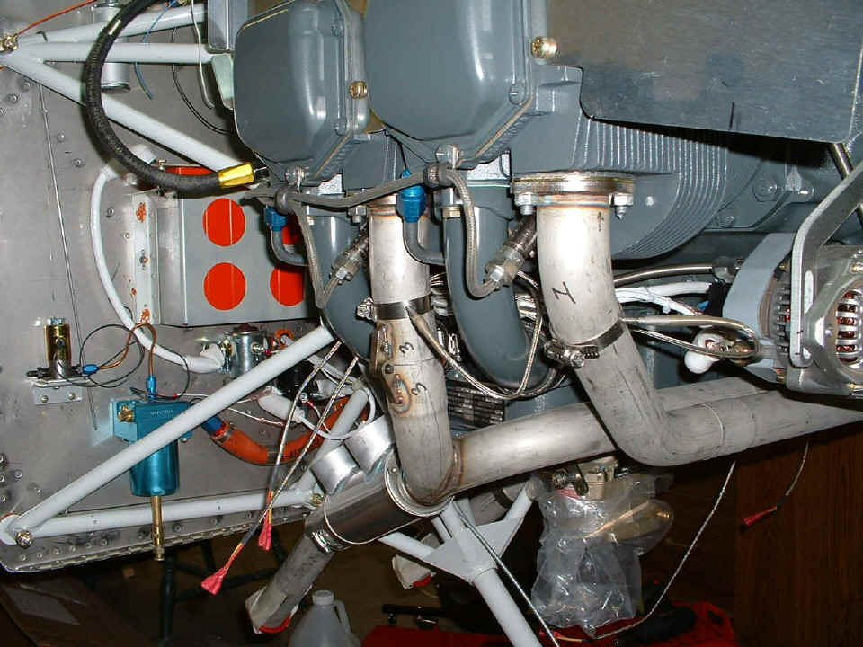
better fit. As for today (Sunday), the first thing was to drill the headers just
about three inches down from the flanges to install the exhaust gas temperature probes
(EGT) and then install the rest of the exhaust system and torque the nuts on the mounting
flanges for what should be the last time on the exhaust system.
I spent much of today's 6.2 hours working to fit some of the baffles in place.
I fabricated two angle doublers and shaped the input plate in front of the number
two cylinder to the approximate shape needed. I also shaped and dimpled the two
doublers (R3B, R3F) and the matching rivet holes on the forward fence that mounts to
cylinder number two. The total construction time stands at
1292.8 hours on the airframe and 1361.8 hours for the complete project, including jigs,
fixtures, work tables, etc.
November 7, 2004: I guess you figured out I was
away on another business trip this past week. I did get some time over the weekend
to get back to work on the airplane. I resumed speed on the cowling and the baffle
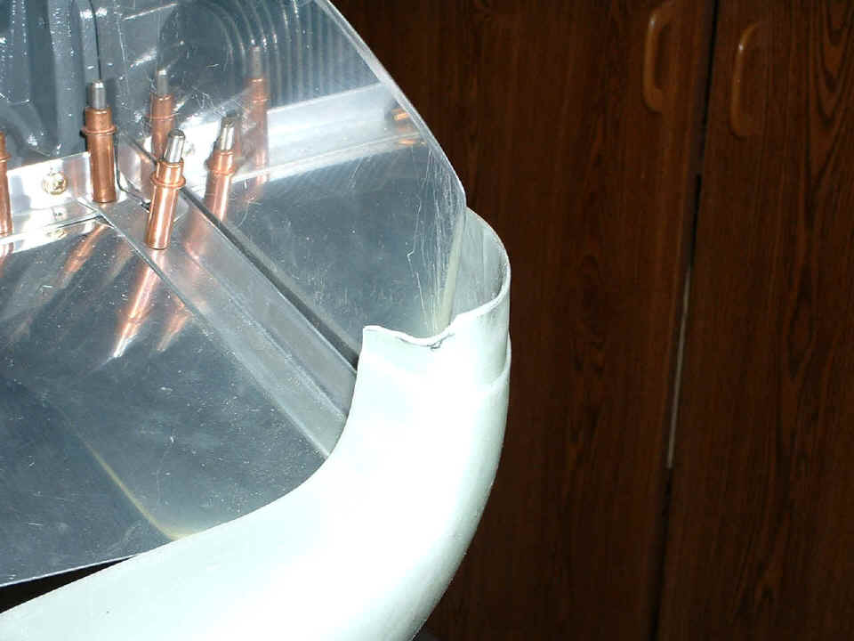
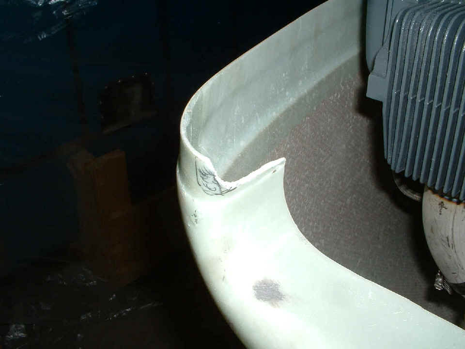
kit modifications to fit my particular cowl. These pictures were taken Sunday night
(November 7th) before turning out the lights near
bedtime. A little bit of black Sharpie ink shows where I have ground away some of
the lip for upper/lower cowl mating clearance in this photo.
Here is the other side after the first cut on it. I have marked the area
for additional fiberglass removal.
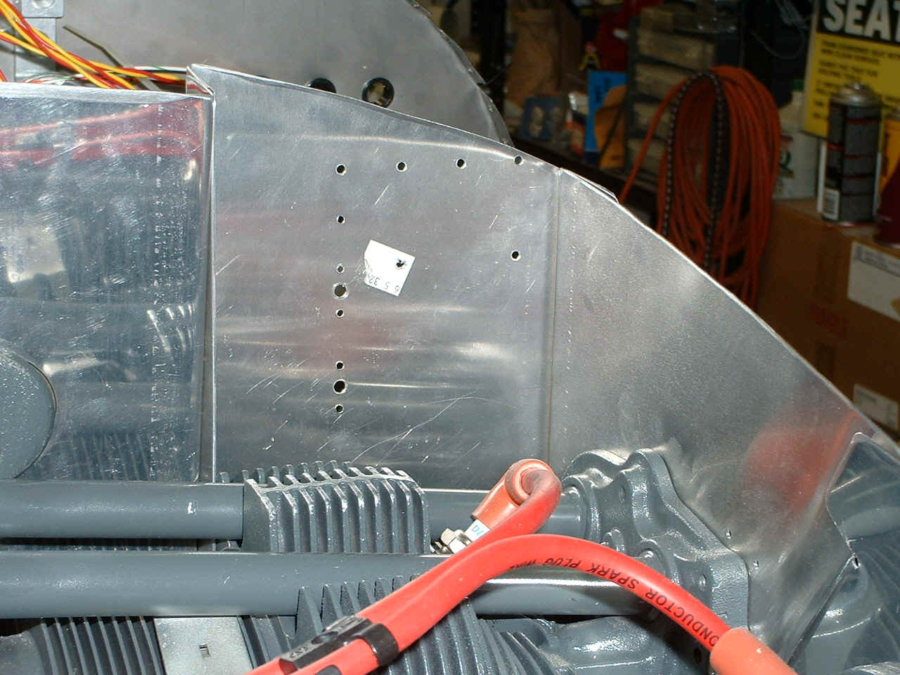
I have been putting the various baffle plates on and off so much during this
part of the cowling fitting exercise. You can see all the holes in the back wall of
the baffle kit where I "thought" the oil cooler would be going. I drilled
two additional holes into the metal showing just how much the oil cooler has to be lowered
to clear the engine mount behind this panel.
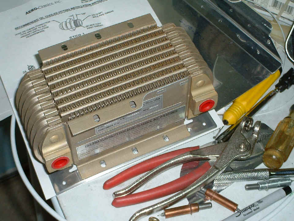
When I looked at the plans and noticed how much of the oil cooler rear mounting
flange would be removed, it gave me the hint as to exactly where to mount the oil cooler.
You can see how the rear mounting flange has been modified per Van's plans to avoid
hitting the engine mount.
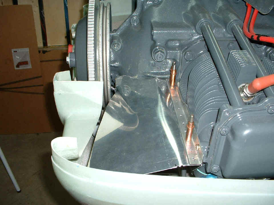
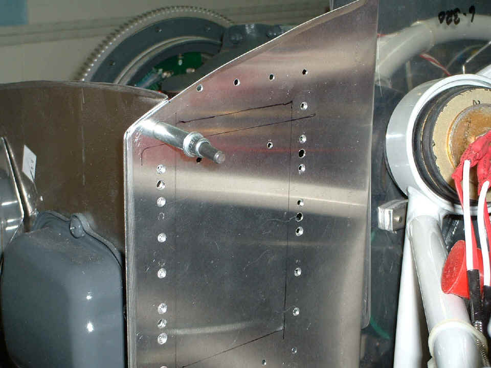
In this photo of the aft side of the LEFT rear baffle, the engine mount is also
in view. The RED plastic cap at the right edge of the photo below is on the end of
the oil line coming from the engine accessory case. That cap is resting on one of
the engine mount steel tubes. The oil cooler flange was removed to allow the oil
cooler to fit under that steel tube, and above the one coming up from the bottom right of
the photo. So the recovery plan for this little screw up is to move the oil cooler
doubler down by the distance between the platenut holes on the right center of the photo
below. The four remaining rivet holes shown near the top of the flange will now be
drilled down at the location just below the silver cleco. You can see that I have
already drilled two of the #30 holes there. The corner holes that were drilled for
platenuts will be enlarged to #30 and any holes not covered by the oil cooler doubler
flange will be filled with rivets or covered by the sealing fabric when it is attached to
the baffle plates..
It was getting late when I stopped the work above. So you will have to wait
until the next session to see the resolution of the oil cooler mounting recovery actions.
That will be on the next page when I publish it. I had
a few visitors on Sunday including a pilot who just ordered his RV-9A empennage kit from
Van's. I took the time to point out some of the hurdles that I wish I had
cleared a bit better and temporarily placed the horizontal stabilizer on the fuselage to
emphasize some points about how the kit is "squared up" for clean flying
characteristics.