New York City Fiber Optic System
February 6, 2012: I have designed a fiber optic network for a major television network. It can bring all the signals from a satellite antenna farm from New Jersey into the master control center for the network in the city. With all the high-rise buildings, getting an unobstructed view of the entire satellite orbital arc is not possible. On this job, I get to mix my satellite experience from 1977 to 1989 with my fiber optic skills gained since January 2006. The work on Monday was to get the fiber optic transmitters in New Jersey up and running via the two fibers going into the city.
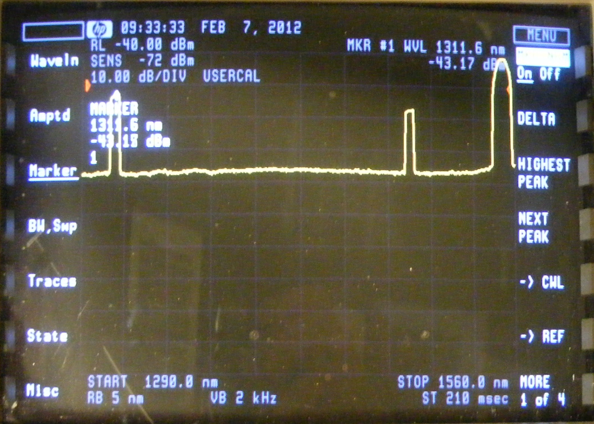
February 7, 2012: This photo has
all the wavelengths from one of the fibers coming from the New Jersey satellite location
into the Fox News Headquarters in NYC. The FAT one is actually TEN DWDM
wavelengths for satellite LNB signals seen in the NEXT photo below. The optical
bandwidth filter used in this photo is wide enough to combine the power of all
ten wavelengths together to display the combined power of the signals taller
than they really are. The calibration of absolute power level is not
correct. The relative amplitude comparison of signals shown is correct.
I took the photo below
showing the optical spectrum analyzer display of the laser beams on different DWDM
wavelengths as they arrived at the network facility in New York City. Each one of
these peaks represents a laser signal that contains 12 or more satellite transponder RF
signals that will be distributed via coaxial cables in this facility. The letters
DWDM stand for "dense wavelength division multiplexing" which is a method to put
multiple laser beams on one single-mode fiber. Each laser beam carries satellite RF
signals that are from different LNB's.

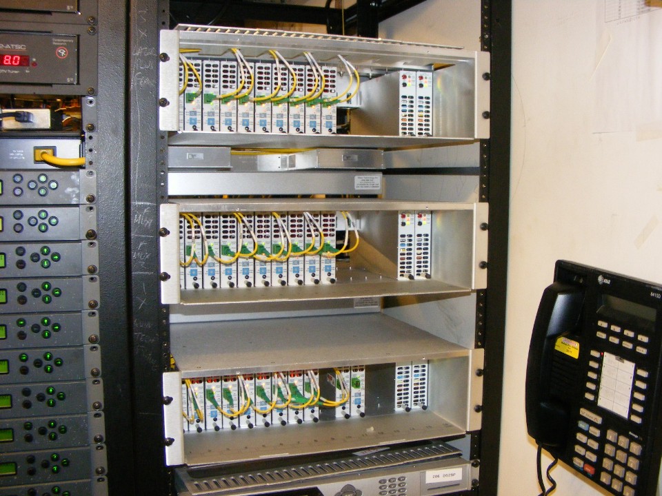
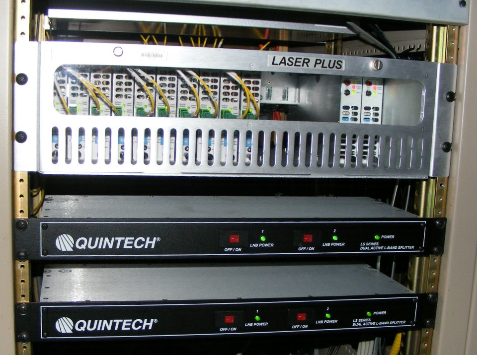
The top LaserPlus chassis in the photo below receives those TEN DWDM
wavelengths seen in the photo above. The yellow fiber jumpers with the green SC-APC
angle-polished fiber connectors are plugged into identical satellite L-Band fiber optical
receivers. A coaxial cable on the back of each module provides the RF signals that
came from various satellite antennas in New Jersey via 12 miles of single-mode fiber.
Another 10 satellite signals are received on a second fiber from New Jersey in the
second chassis below. The third chassis will receive eight satellite signals from a
satellite uplink in nearby Connecticut. One satellite uplink optical signal can be
sent from here to that uplink in Connecticut. That one optical signal currently
carries FOUR satellite RF uplink signals that support four different cable channels.
All three chassis contain dual-redundant AC power supplies. There are some modules
between the chassis that will be seen in the photos below this one.
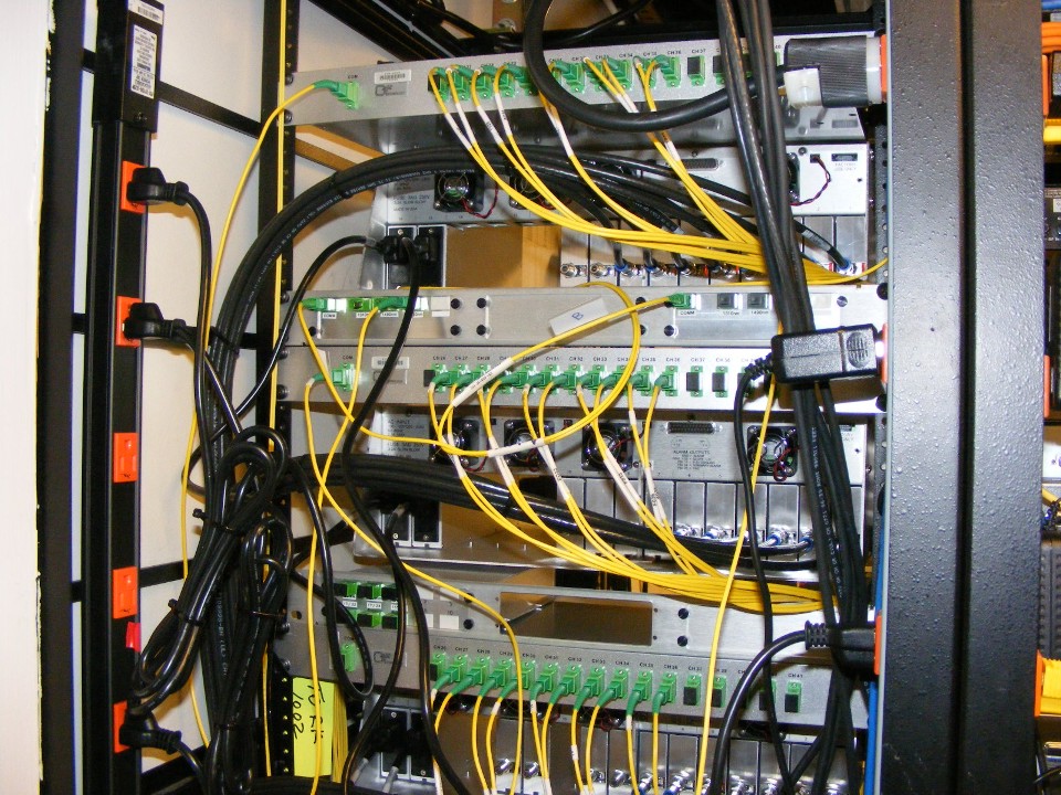
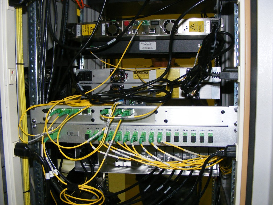
The view of the rear of this equipment rack shows two 16-port optical demux
devices that actually separate the optical wavelengths seen on the optical spectrum
analyzer photo above. The input port from the DWDM fiber optic transmitters in
Secaucus, New Jersey is the single fiber optic cable on the left side of the demux chassis
at the top of the photo below. The first chassis seen at the top of the previous
photo is just below the first DWDM demux in this next photo. Each yellow fiber optic
jumper has a printed label identifying ONE optical wavelength ITU channel number and the
satellite feed from the antennas in New Jersey. Each of the two fibers from New
Jersey has 10 DWDM wavelengths. Look at the 1-rack unit frame with two smaller demux
devices that is level with the second orange power plug. Those two smaller
demux devices separate laser beams at 1310 nanometers (nm) and 1490 nm from the DWDM
wavelengths in the 1550 nm range. The 1310 nm wavelength transports CATV signals,
while the 1490 nm wavelength provides a gigabit Ethernet connection. A large bundle
of RG-6 coaxial cables connect the RF output signals of each optical L-Band satellite
receiver to the RF distribution network in the facility. Each coaxial cable carries
multiple satellite RF transponder signals from ONE polarity of a satellite antenna.
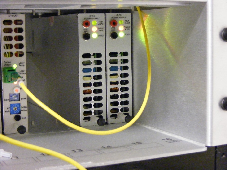
Here is a close-up photo of the two power supplies in the bottom chassis.
I mounted my camera on a tripod and took this photo without a flash to show the
normal indicator lights on the power supplies. The module at the left side of the
photo is a transmitter to send signals to the uplink antenna located in Connecticut.
This job in New York City lasted a total of three days on two different sites. I left the city on Wednesday afternoon and ran into snow in New Jersey as I began my journey back to Virginia to return the optical spectrum analyzer to our director of engineering at his lab. I got home on Friday evening just after 7 PM.
July 10, 2012: I was back in NYC for three
days to complete the second phase of the fiber optic system. Yesterday, July 9,
2012, the equipment was installed between a satellite uplink in Connecticut and the main
facility in NYC. I did not take any photos of the transmitters for phase 1 in New
Jersey when I did the initial installation in February 2012. On Tuesday, July 10, I
was back at that New Jersey site and took a couple of photos of the equipment that sends
the optical signals to NYC. The next photo shows 10 fiber optic transmitters and two
power supplies in a chassis located in a television control room in Secaucus, NJ.
These are half of the satellite signals being sent to NYC.
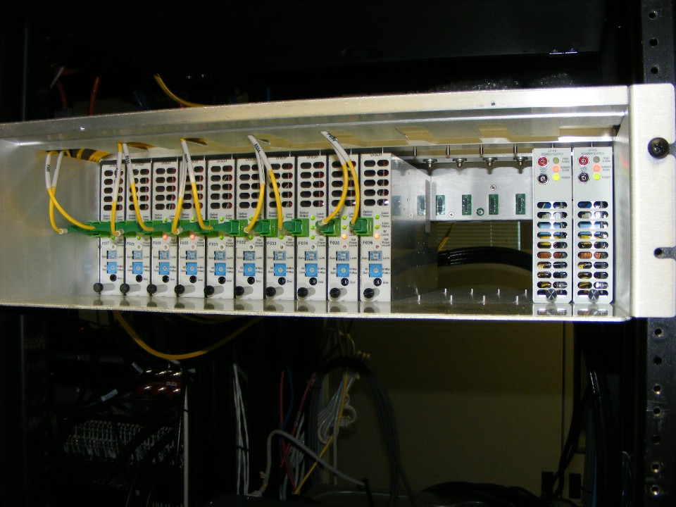
The next photo has another 10 fiber optic transmitters
located upstairs in an equipment room. This photo shows the built-in fiber
management tray above the modules with fiber entry slots at both sides of the chassis.
There are slots on the top and bottom of each module that use the guide pins above
and below each module slot. Slot 16 at the far right side of the chassis accepts
only a power supply module. Slot 15 can accept a power supply or any other type of
LaserPlus module. This chassis shows dual power supplies in a load sharing
configuration for redundant power supply operation. Power supply modules cannot be
inserted into slots 1 through 14 from left to right as seen from the front of the chassis.
This photo shows the rear of the chassis seen in the photo above, and the
optical combiner that couples all TEN optical wavelengths from this chassis onto a single
small BLUE fiber headed for NYC from the isolated green fiber connector at the upper left
corner of the photo below. The camera flash created a shadow of the blue fiber just
above the OT label
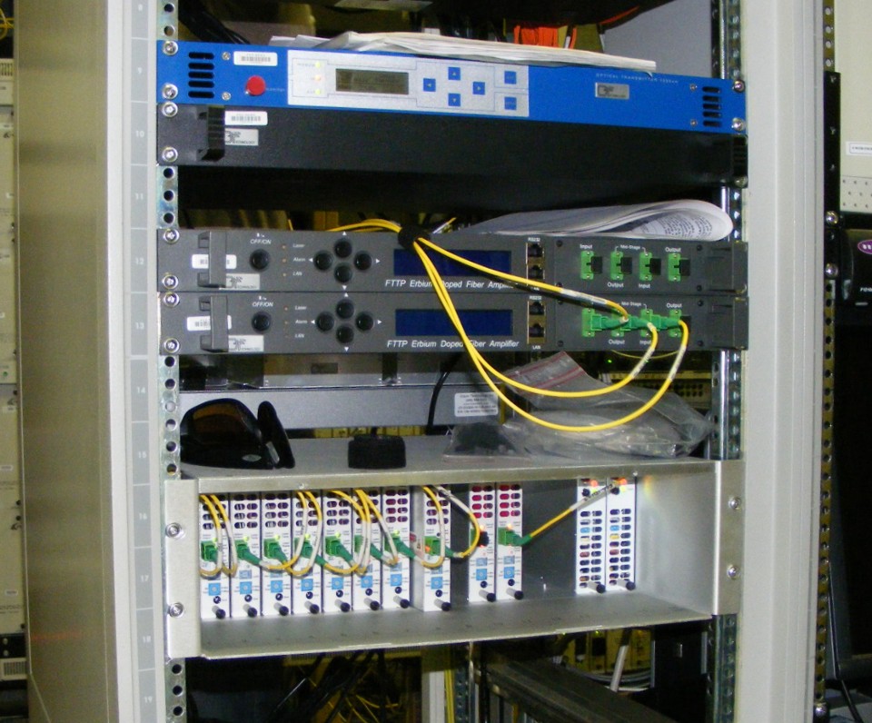
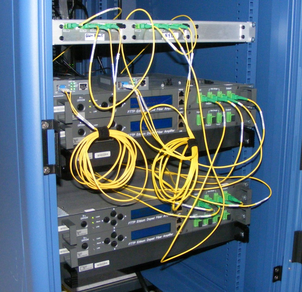
The equipment for the other fiber link between NYC and Connecticut is shown below when it was installed on Monday morning, July 9, 2012. The blue chassis at the top will send CATV signals to NYC. The two black units with the green optical connectors on the front are erbium-doped fiber amplifiers (EDFA). One EDFA is used to transmit the optical signals to NYC, and the second identical EDFA is a spare. At the bottom of his photo is another LaserPlus chassis with nine optical transmitters, two optical receivers, and two power supply modules. The signals from that chassis are connected to the similar chassis at the bottom of the second photo near the top of this web page.
This location in Connecticut is a satellite uplink used by several of the major
television networks here in the USA. Eight of the nine transmitters in the chassis
below send satellite LNB signals received at this location into NYC. You can see one
of transmitters is pulled slightly forward to turn off the power to it since it is a spare
unit. The two receivers in the chassis can receive satellite signals created in NYC
and pass them to the uplink here at this location. Only one receiver will be in
service. The second one is a spare and will be powered down at the end of initial
testing.
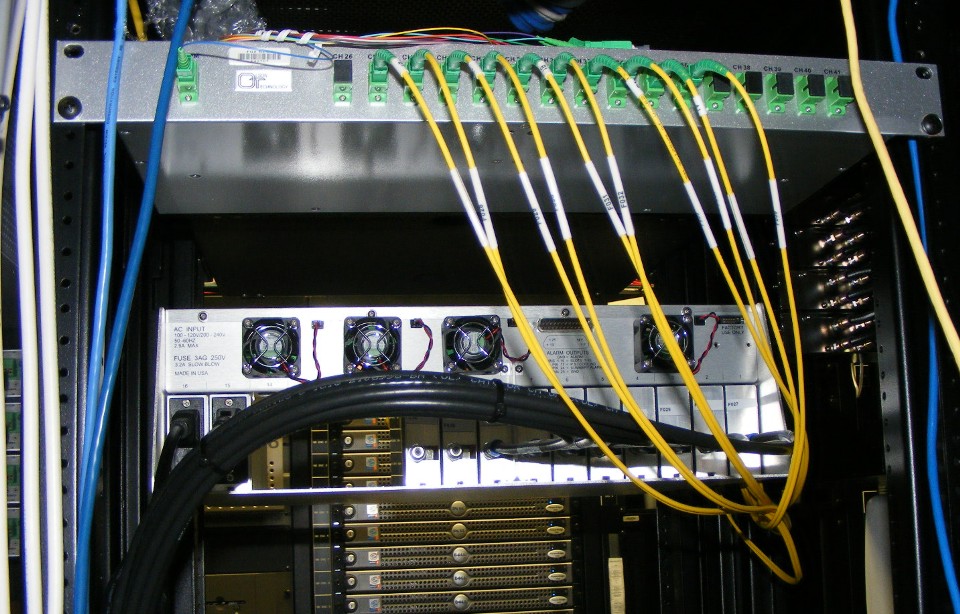
Here is the back of that same equipment rack showing how all the fibers connect
together before ONE fiber goes to the input of the EDFA. There are two wavelengths
that provide a gigabit Ethernet fiber optic data link between NYC and this location in
Connecticut that do not go through the EDFA. That fiber coming from NYC also carries
the satellite uplink signals. The small media converter module that provides this
GIG-E data link is partially hidden by the power cords. Look carefully and follow
the pair of fibers with blue connectors on them as they plug into the SFP digital
transceiver on the media converter module.
The distance between the satellite uplink in Connecticut and the facilities in
NYC is over 120 km (75 miles). As a result of that distance, there is a location
about half way along that fiber route where there are more EDFA's to boost the signals
going south to NYC on one single-mode fiber, and to boost the one optical signal carrying
the northbound satellite RF uplink signals on a second single-mode fiber. The
northbound fiber is routed into a MUX at the center of the 1-rack unit frame at the top of
the photo below. The MUX separates the two GIG-E data wavelengths and feeds them to
the media converter module seen on top of the two EDFA's at the center of the photo.
The media converter that regenerates the binary data signals to optical wavelengths going
to Connecticut is to the left of that first one on the top EDFA. The RJ-45 data
connections from these media converters will be connected to a Cisco router to be
installed later. Once the router data links are installed, the equipment located
here and in Connecticut can be remotely monitored from NYC. Today was the day the
fiber optic links were established, the data link activation comes later.
The two EDFA's at the bottom of the photo above amplify the southbound optical signals going to NYC. The southbound fiber has no muxes at this location as only DWDM wavelengths are being transmitted on that fiber. The input fiber to the bottom EDFA's is coming into the building from Connecticut and the output fiber leaves the building going to NYC.
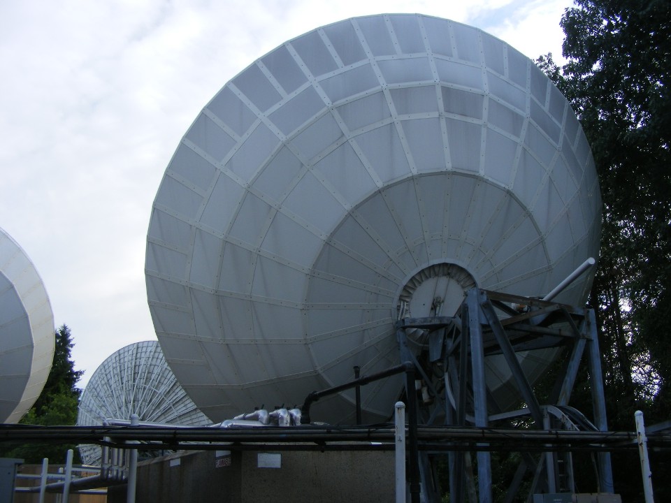
Tuesday afternoon, July 10, I needed to go back to the Connecticut site for some additional tests and adjustments. When I was there, I stepped out the back door of the building to take the next photo below. The satellite dish antenna nearest the camera is heated for winter conditions to keep ice and snow from sticking to it. The accumulation of the ice and snow defocus the satellite RF signals coming into the dish and leaving it going up and RF downlink signals from the satellite in geostationary orbit above the Earth's equator. The result is a lower power RF signal in both directions.
Each antenna at this location points at a different satellite. All those satellites are at an orbital altitude of 22,279 miles above the surface of the Earth. At that orbital altitude, the satellites take 24 hours to make one orbit of the Earth. From the ground stations, the satellites appear to stand still directly in front of the satellite antennas on the Earth. We rely on the signals from those satellites to feed TV network channels and other communications to places over much of the planet. Due to the curvature of the Earth, satellite signals from geostationary orbit cannot be seen at latitudes greater than 81 degrees north or 81 degrees south of the equator.
Not too many folks live at those polar latitudes. There are ways to get
satellite signals to those remote outposts in the Arctic and Antarctic regions using
multiple satellites in highly-elliptical polar orbits. Those satellites orbit north
and south around the Earth. Back in the 1980's when my job was in the satellite
communications industry, the Russians had a group of polar-orbiting satellites named Molniya to feed communications to
their far northern villages north of 81 degrees latitude. Those satellites would
come down close to the Earth only a few hundred miles over Antarctica. When the
satellites would come up to the north, they would be at an orbital height of about 24,800
miles. A satellite up that high slows down and moves very slowly across that part of
the northern sky. Using multiple satellites synchronized in that same orbit, when
one satellite starts to come back down from that part of the orbital arc, another
identical satellite comes up to take its place. The user on the ground does not
notice the change from one satellite to the other as they sail in front of the fixed
antenna on the ground. The Molniya satellites also had UHF television transmitters
on them allowing ordinary roof top TV antennas to receive signals without a small
parabolic dish antenna similar to these really big ones. Those UHF ground antennas
point UPWARD at an angle to get the best reception. ALL other home television
antennas on the Earth are aimed at the horizon.
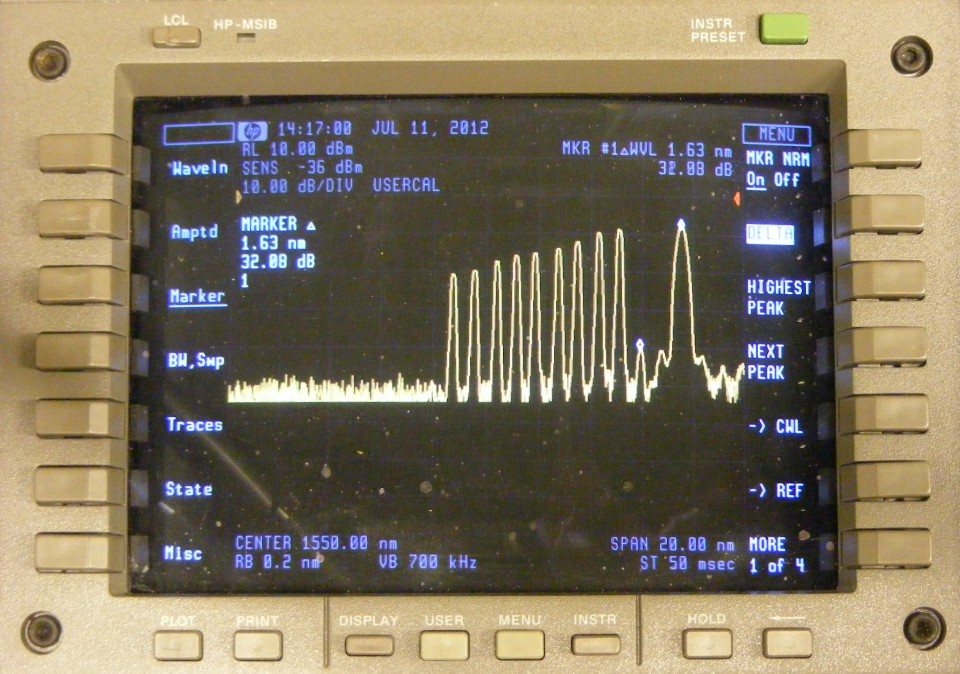
My last day on the three-day trip to NYC was Wednesday, July 11, 2012.
This is the group of optical signals as they arrived from Connecticut. The tallest
optical signal will bring the CATV RF signals to NYC. The other signals will bring
satellite RF signals from the satellite antennas. The little peaks seen near the
tallest one are third-order optical signals resulting from going through TWO EDFA's to get
across the 120 km of fiber from the site in Connecticut to this location in mid-town
Manhattan in NYC. The strongest of the third-order signals is measured here at about
32 dB below the strongest original signal. At that signal level, it does not affect
the quality of the original signals from Connecticut.
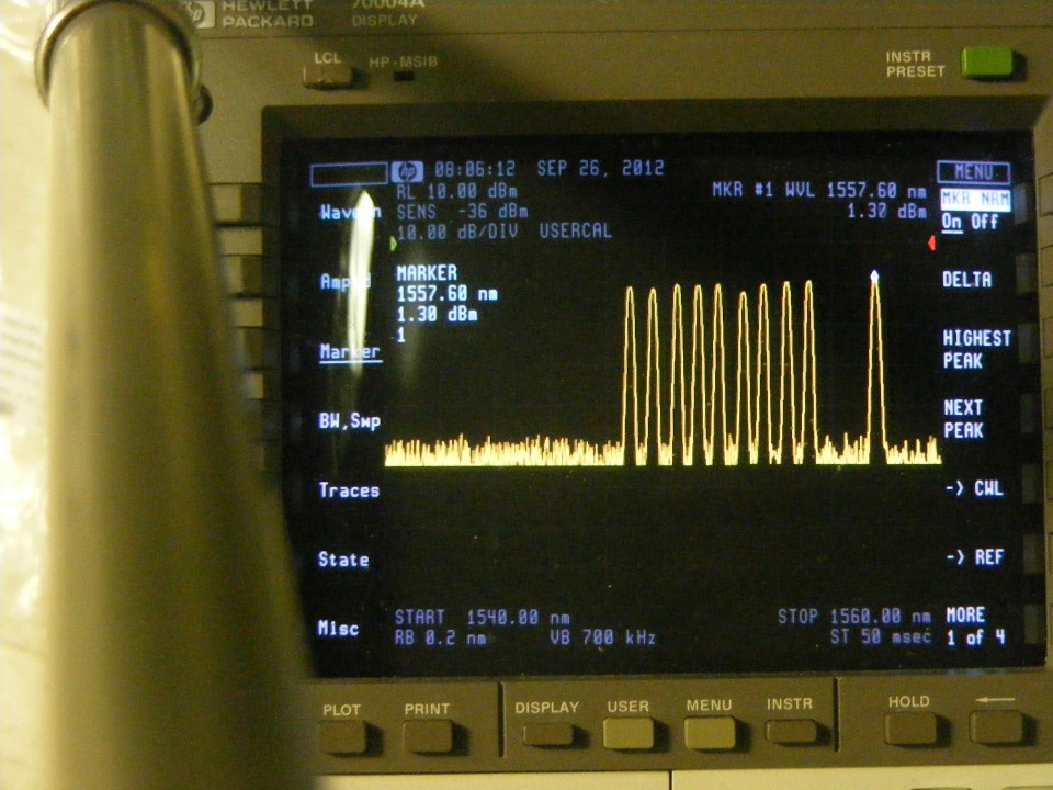
September 26, 2012: I returned to the
satellite uplink location at the north end of the 126 km fiber path to correct the optical
response slope from the launch EDFA. This photo shows the output of the first stage
of a mid-stage EDFA. A dispersion compensation module is also in the optical circuit
and an optical pad to present the signals you see here to the second stage of the EDFA.
The 16-port DEMUX from New York City has been installed here to pre-slope the
optical signals going into the EDFA. That change will optimize the performance of the
total optical fiber link. The goal is to reduce the third-order optical distortions
in this first EDFA.
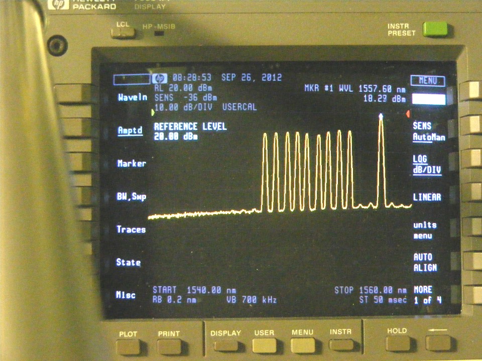
This second photo today shows the output of the 24 dBm output stage of the
first mid-stage EDFA. The marker is reading the power of the ITU 24 signal that
carries CATV service. Take note of the downward slope of the noise floor of the
EDFA, yet the optical carriers are still relatively flat. The amount of third-order
distortions (bumps on the base line) are also lower than before the exchange of the two
16-port muxes from each end.
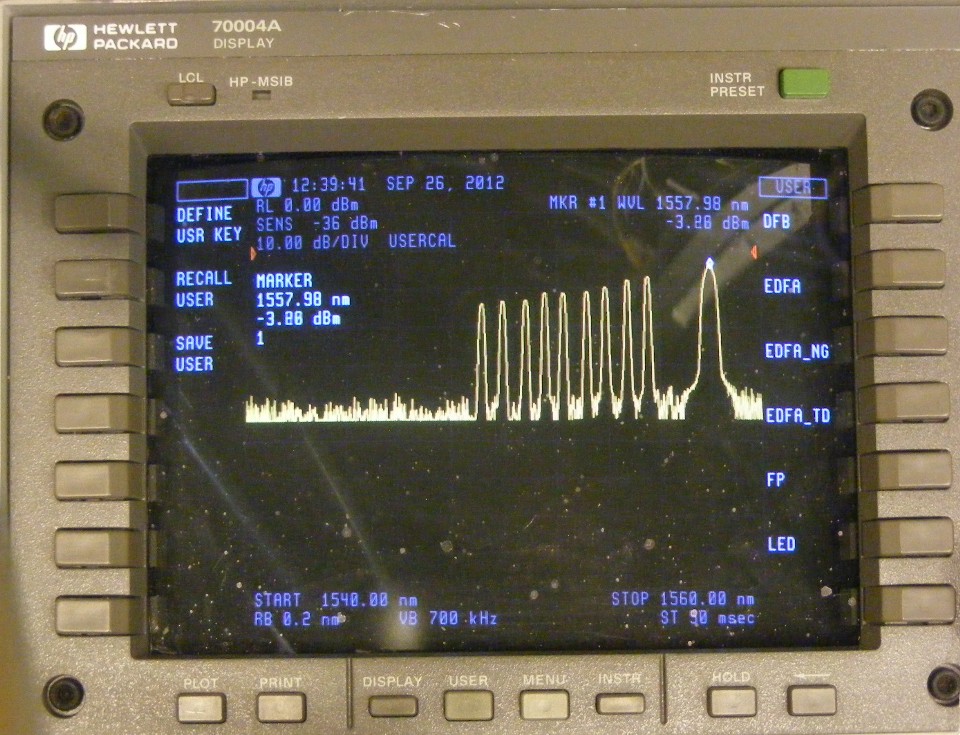
Finally, the end result of the exchange. These are the signals after 126
km of single-mode fiber and passing through two EDFA's.
| Return to Technical Articles | RETURN to PAGE 356 | Return to MAIN MENU |