Columbus, Ohio - Preparations · · PAGE 2.
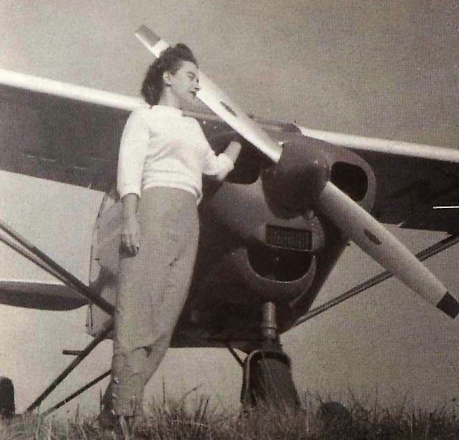
1956: Any great adventure requires some
risk. Managing that risk is what a student pilot learns beginning with the first
flying lessons. It was seven years before her historic flight when Jerrie was
learning to fly in this Piper Tri-Pacer. This was an early nose-wheel airplane when
most airplanes before this one had a tail wheel with two main landing gear wheels up
front, ahead of the wing, and behind the engine. She wanted to become a pilot since
her first airplane ride as a child.
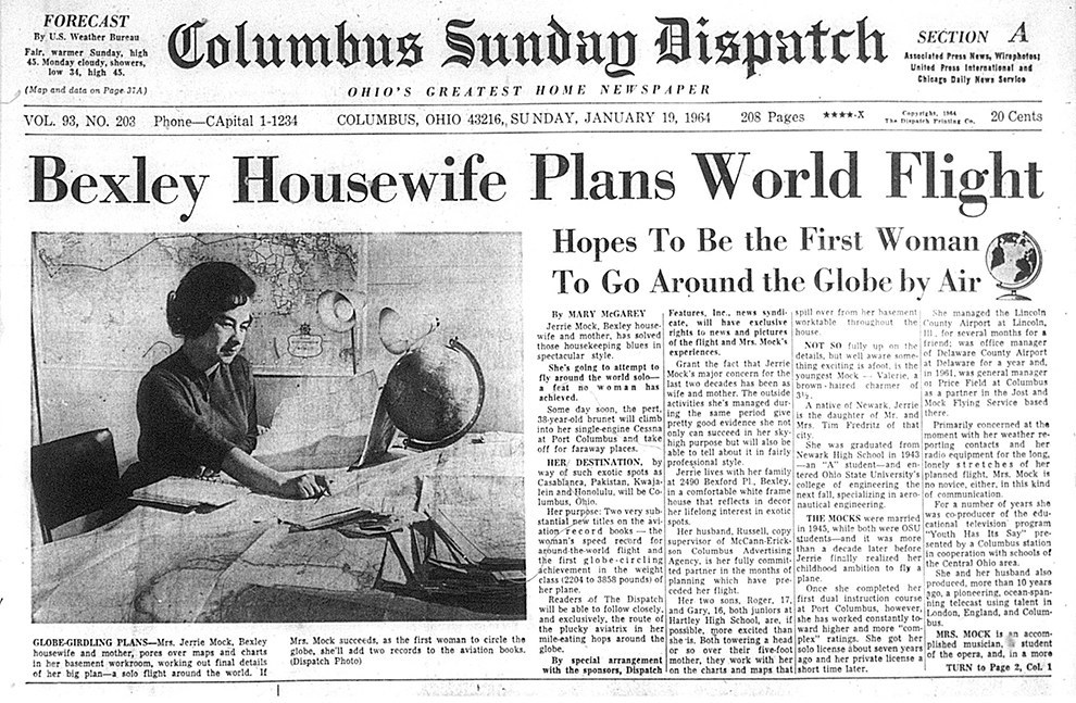
January 19, 1964: The other kind of risk in setting a world record is the need for a sponsor. There are sponsors that sell airplanes and aviation parts, etc. The Columbus Dispatch was the major sponsor for Jerrie's around the world flight. Articles like this one would spur public interest in her world record flight. That photo on page 1 shows her at home with many of the aviation charts (maps) that she would need as she travels around the world on her great adventure. She had help from some of her friends in the US Air Force advising her on the best routes to fly. Jerrie's home is the Columbus suburb of Bexley, Ohio.
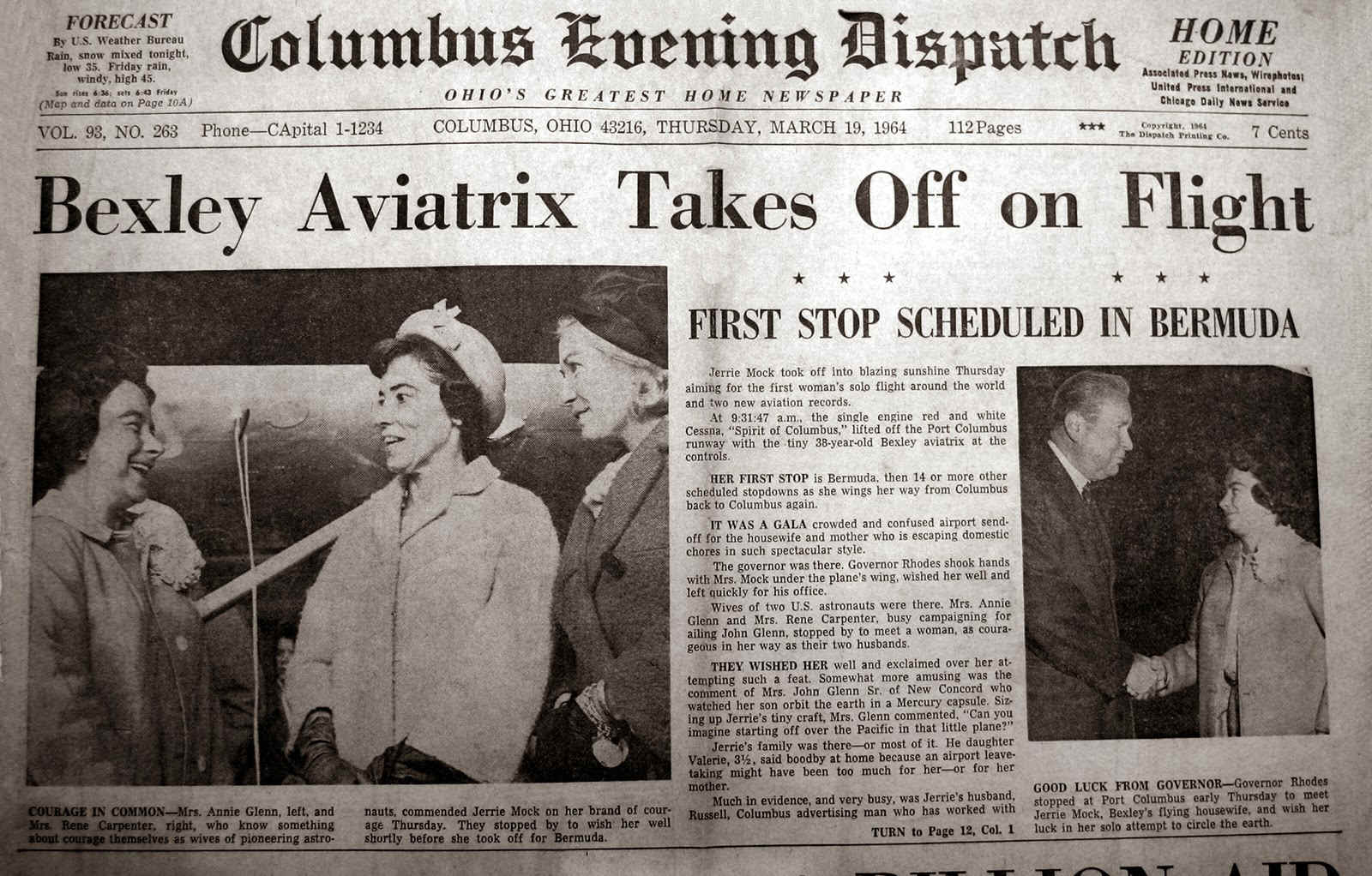
March 19, 1964: Of course the newspaper wanted
lots of pictures and stories from wherever she went as she flew around the world.
Good stories help sell newspapers. Guess who got the banner headline on page
one the day she took off for the big journey.
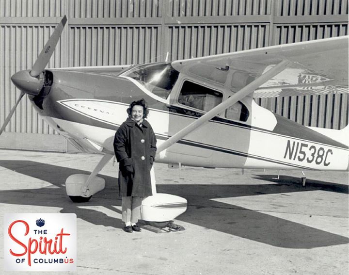
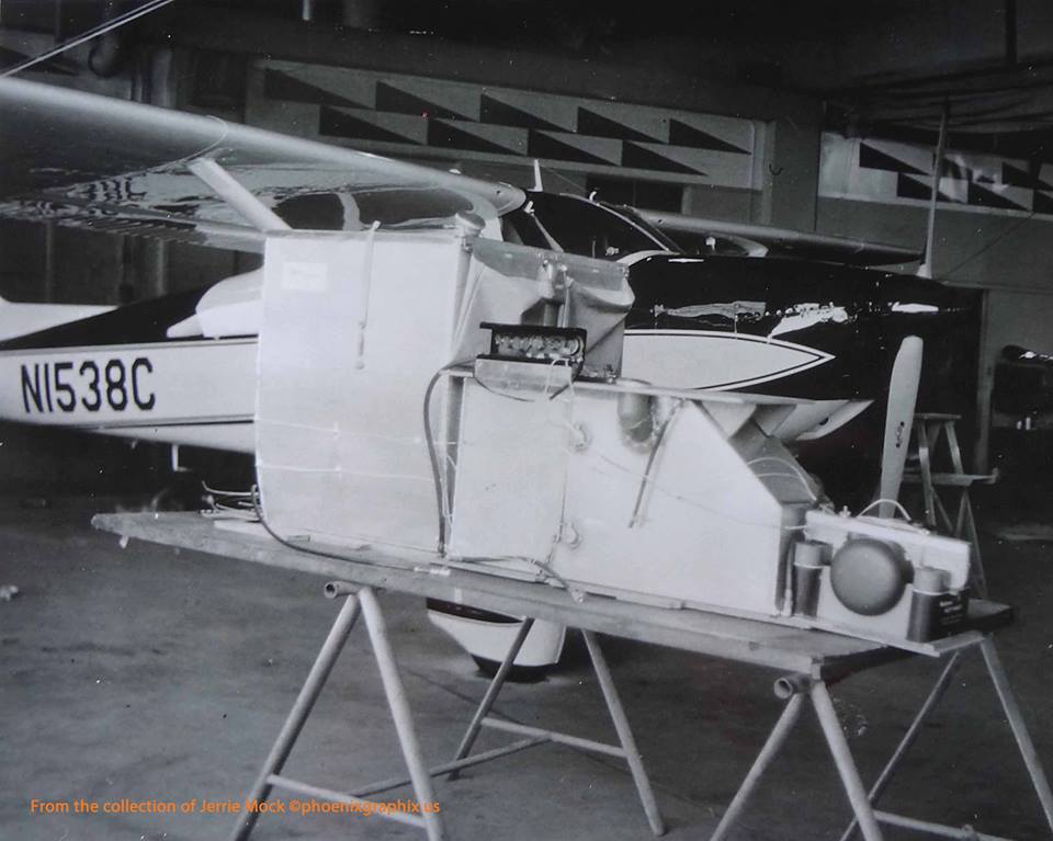
This is a photo taken during a final check with the crew that prepared the
airplane for departure from Columbus, Ohio. The long-wire antenna for the H.F.
(short wave) radio hangs down from a tube near the tail. Notice the heavy coat she
is wearing due to the cold temperature that day in March 1964.
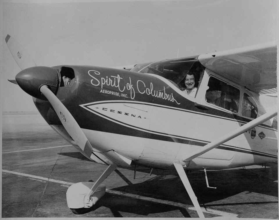
The photo above and the one below show the two low-frequency ADF antennas. One on the top of the airplane is partially hidden by the wing. The antenna on the bottom of the fuselage has yellow circles to show the ends where a long thin wire is connected between the ends. There is a second antenna for each of the long-wires, and that antenna is very small and appears here as a thin, flat rectangle on the bottom of the airplane above the word STEP (the left one) in the photo above. That same antenna is visible in the photo below with the front end of it near Jerrie's right arm and the other end of it below the letter "N" of the aircraft registration number. That end of it has a white post sticking down and bent toward the front of the airplane with the thin wire stretched between the two locations. There is a metal step below the side door on both sides of the fuselage to assist in getting in and out of the cockpit. Just behind that step on the bottom of the airplane in the photo below is a short plastic antenna cover with a black dot on it. Inside that cover is a small antenna for a 75 MHz marker beacon receiver. It is used when flying an ILS instrument approach for a landing in IFR weather conditions at an airport equipped for those landings.
Look below the numbers 5 and 3 and you will see something that looks like a
cone hanging down from a tube in the shadow of the airplane. That is another view of
the long-wire antenna for the H.F. radio that can be reeled out for flight over the ocean
when long range communications are needed. That antenna is retracted before landing.
The cone keeps the long antenna wire straight behind the airplane in flight.
Adjusting the length of the wire tunes it for the proper short wave frequency for long
range communications with air traffic control over the oceans or any remote area on the
planet.
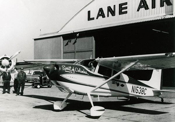
This photo that was on page 1 of this section is seen here showing details that
she mentions in chapter 1 of her book about the last-minute preparations, including taking
photos like this, etc. The airplane was on the ramp in front of Lane Aviation in
their previous location on the north side of the Columbus airport in 1964.
I was looking at the photo above this morning (14FEB2015) and realized how many
things she mentions in chapter ONE. Take a look at the FOOT hanging out of the door
behind her. There were so many things going on during the final preparations before
departure. The guy with the foot hanging out was working on the light for the
compass as she will be flying at night and needs to confirm her course. The other
little detail in the photo above is about the ADF antenna wire I talked about higher on
this page. Here in the photo above, you can actually SEE the thin wire
antenna. There are a couple of men behind the airplane. Behind them, there is
a black pickup truck. Look above the wheel of that truck and you will see the ADF
wire antenna stretched back from the front post.
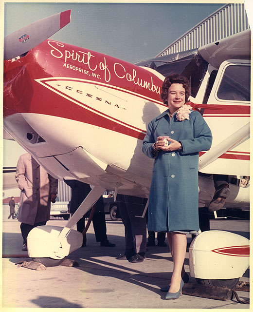
The photo below was snapped before engine start and taxi to the runway for
takeoff from Columbus, Ohio. This photo was staged for the newspaper. The
first leg of the journey was a non-stop flight of 1,160 miles to Bermuda in the Atlantic
Ocean. This photo is posted on the Fly38Charlie
Facebook page. Jerrie has a good description in Chapter One of her book of what
happened shortly after this photo was taken. It describes the realization that her
dream of flying around the world is actually beginning with the fundamental things all
pilots must do before each flight.
Flying from Columbus, Ohio to Bermuda
The photos and hand-shaking with dignitaries are completed and it is time to
go. The photo below shows her wearing her inflatable life vest, a hat with a brim,
and sun glasses. With the engine running, she calls ground control at the tower on
the VHF radio to get permission to taxi out to the runway prior to take off and departure.
Since the airplane was heavily loaded with fuel, the ground controller gave her
clearance to taxi to the longest runway at the Columbus Airport.
I looked back at older Google Earth images to find this one from 2002 which
matched the taxi instructions given to Jerrie by the ground controller. She moved
the airplane from Lane Aviation on the north side of the airport to the west end of runway
NINE RIGHT, south of the passenger terminal buildings. Here is my visual image of
the taxi route she was given on March 19, 1964 overlaid on an image of Columbus Airport
from 2002. Not all the aerial photos were in color that year.
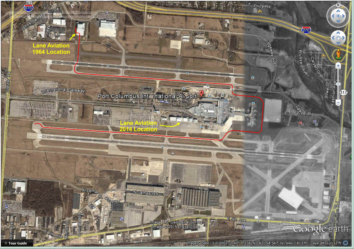
When you read this book, you will "hear" Jerrie talking to herself when she is doing the final checks of the engine and radio frequencies down at the end of that longest runway seen in the image above. The end of the RED taxi line is where she completed the pre-takeoff checks. When she was satisfied everything was ready (including herself), she called the tower and was cleared for takeoff. The details of what happened next is another reason to read the book. There are too many interesting details to put into these web pages.
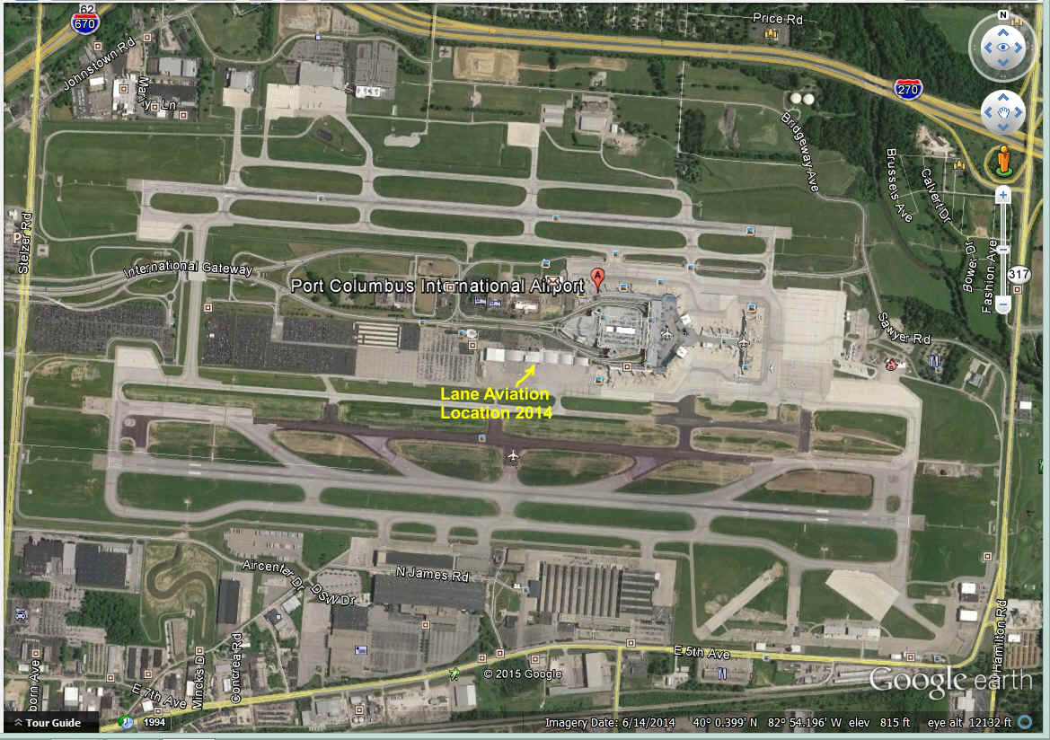
Columbus Airport has changed since 1964, but it was essentially like that 2002
image above when Jerrie began her adventure in 1964. The Google Earth image below is
from 2014. A lot of changes are seen below compared to the airport as it was when
Jerrie began her flight. The change in magnetic variance from 1964 to 2014 has
resulted in putting new numbers on the Columbus Airport runways. Runway NINE RIGHT (
9R ) in 1964 is now labeled as runway TEN RIGHT ( 10R ). The magnetic north pole of
the Earth drifts over time compared to true north. That change in the magnetic
variance at different locations on the Earth affects the accuracy of a magnetic compass
wherever you travel. The variance is shown on aviation charts allowing pilots to
compensate and change their course heading as needed.
May 25, 2015: UPDATE! I have been working on a new project related to Google Earth. My "flight following" of Jerrie Mock on her 1964 flight around the world was greatly enhanced by the Google Earth images that were first published to these pages. I kept wishing there was more I could do to share the adventure with all of you reading this page NOW!
I recently discovered the "TOUR" feature in Google Earth and its ability to follow recorded GPS track files showing the view from any airplane in flight. My first "tour" was the 2007 trip to Alaska, a 50-page story with about 500 photos taken by Wendell and Terry on that five-day flight. The GPS files for that trip have been edited to compensate for GPS altitude errors vs. Google Earth airport elevation data points. Some airports as seen from a takeoff or approach to landing clearly show those ground elevation errors as a "roller coaster" look of up and down "waves" in the length of the runway. I have recently finished processing Garmin GPS log files from a 2005 trip to New Mexico for touring in Google Earth. What I learned from both projects is how to create GPS files where none exist. With that new knowledge, I have been able to create missing GPS flight segments for the Alaska trip and my LOE5 flight to New Mexico. That is what I have done for Jerrie Mock as you can see below.
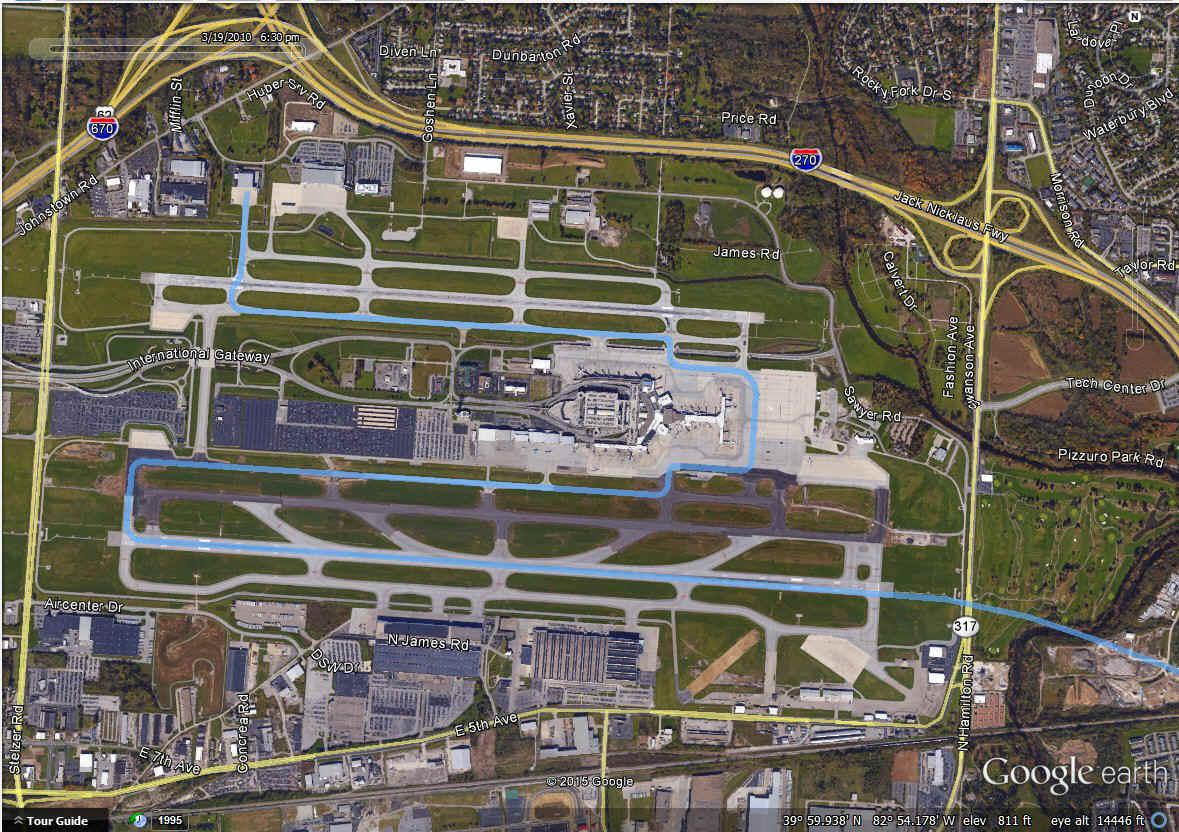
Here is her taxi route recreated to match the current version of the Columbus, Ohio Airport depicted in Google Earth. This is more than the red line seen in an earlier image above. This is a GPS log file that continues a "flight" to Bermuda following the same route Jerrie described in her book "38 Charlie". The best part is YOU can share her flight using Google Earth as I have done. Follow that link in the previous sentence to prepare for YOUR flight with Jerrie Mock. CLICK on the next link to download this ZIP file ( Jerrie_Mock_Flights.zip ) and follow the instructions on my How to Fly Google Earth web page. This new ZIP file now contains several files for the flight from Casablanca to Bone. The files show how that area has changed since her flight in 1964 and the better graphics that have been updated between the years of 2007 and 2014.
We did not have GPS to guide us in 1964, but I have been able to create the
files needed using the tools in Google Earth and some computer work with Garmin MapSource
and other programs. The images below show how Jerrie's Google Earth tour flight
begins for all of us today. I hope YOU have a GOOD computer with 3D video capability
as there is MUCH to see departing the Columbus Airport as it seen today in Google Earth!
Here is the Google Earth view of the NEW runway TEN RIGHT as it looks to a
pilot departing Columbus, Ohio in 2015. This screen capture is from my Jerrie Mock
"GPS" departure file using the Google Earth tour function.
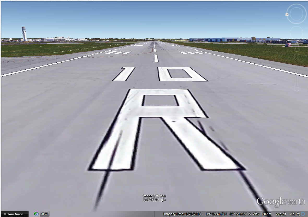
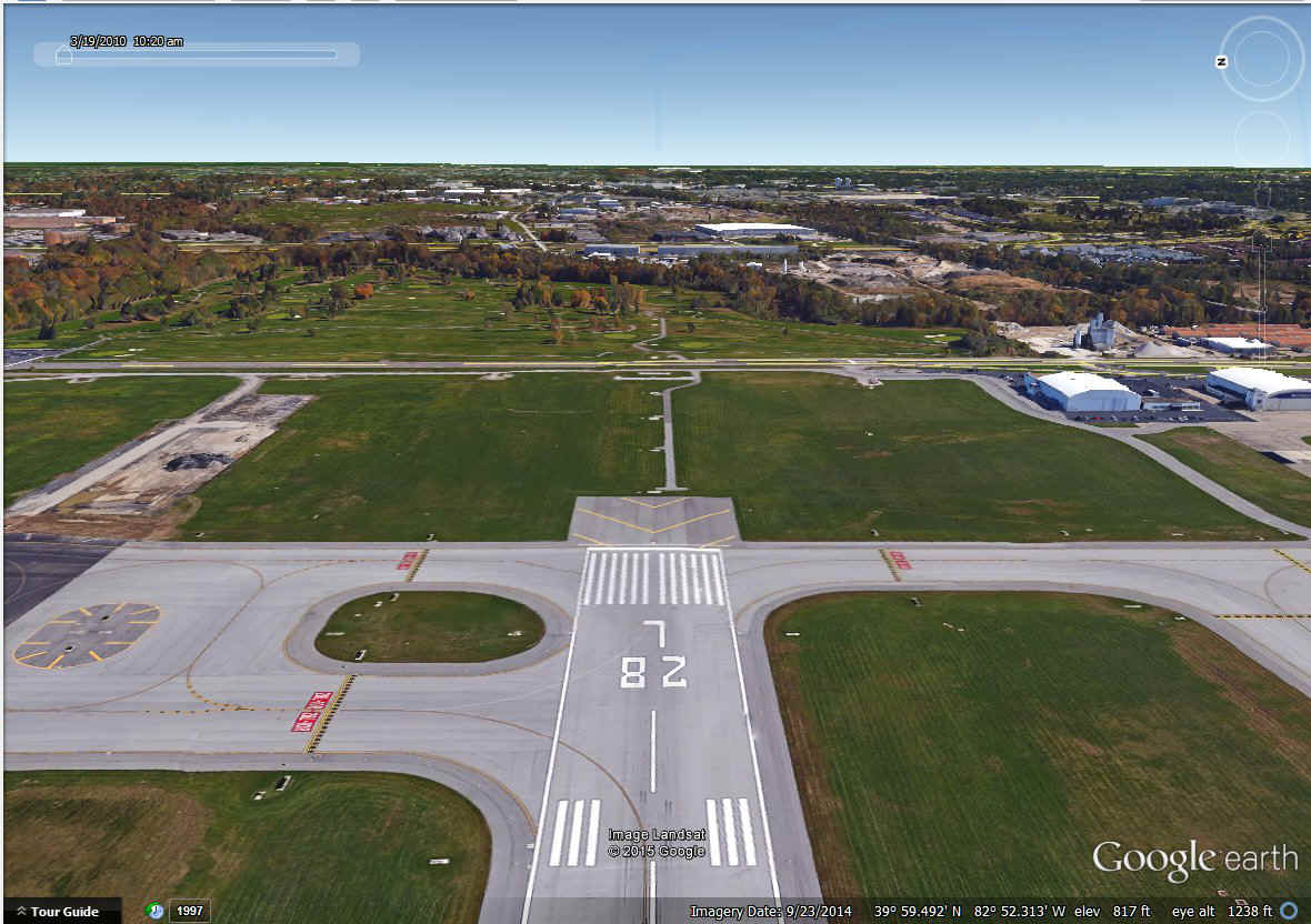
As Jerrie flew her Cessna 180 climbing out from the airport, the other end of
the runway was marked 27L for TWO-SEVEN LEFT. The image below from Google Earth
shows the current markings for this runway. The changes in the magnetic
field of the Earth since 1964 required a change to the runway number. Beyond the end of the runway is a golf
course in this imagery from September 23, 2014. There are some beautiful scenes
ahead crossing the Ohio River near Parkersburg, West Virginia and into the mountains in
West Virginia and Virginia. The date and time of the imagery varies along the
route. The image dates along her route during this virtual flight are shown at the
bottom of the Google Earth screen.
When she reached Virginia she mentioned Richmond up ahead to her left.
She wanted to test the high-frequency radio before she started out over the Atlantic
Ocean. She discovered the high-frequency radio did not work at all. Her course
took her over the Dismal Swamp south of Norfolk, Virginia and across the Elizabeth City,
North Carolina airport where a US Coast Guard Station is located for air/sea rescue.
The Elizabeth City airport has this VOR (VHF Omni Range) transmitter used for radio
navigation located on the airfield as seen below.
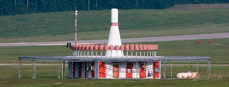
This is a photo of the VOR transmitter located at the Raleigh Durham Airport in
North Carolina. The VOR at Elizabeth City is similar to this one. The propane
tank is there to power a generator in case of a local power failure. The circular
metal grid around the antenna provides a good "ground plane" for proper signal
transmission. The words "Ground Plane" have nothing to do with any kind of
aircraft. The signals that are transmitted from this station are for use by aircraft
in flight.
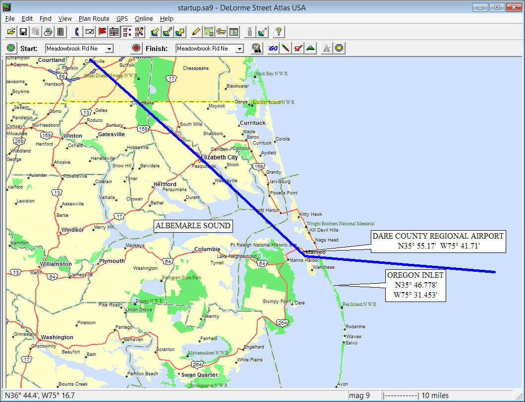
There is also a VOR located at Dare County Regional Airport (KMQI) in Manteo, North Carolina on an island
in the Roanoke Sound. It is the VOR in the USA that is closest to Bermuda. The VOR
(RBX) is named for the Wright Brothers who had their first powered flight not far from
here in 1903. It is a good place to set a final course before heading out over the
ocean. There is also an NDB (non-directional beacon)
located on the airport. Just beyond the airport is the barrier island that leads
south to Cape Hatteras. Jerrie commented about it as she flew out to sea toward
Bermuda. She talked about being over a bay or inlet as she departed the USA.
That inlet she mentioned is between the barrier islands and visible in the upper right
corner of this Google Earth image below. It is named Oregon Inlet, even though the
State of Oregon is on the other side of our country on the Pacific Ocean, but that comes
later in the story.
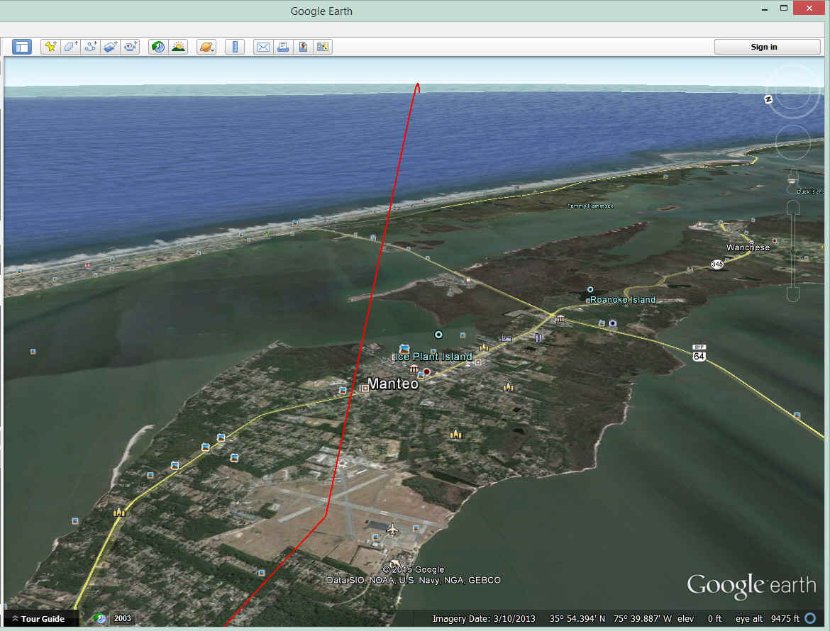
| May 25, 2015 UPDATE! The RED line seen in the image above is a course line I used in my original Google Earth tracking of Jerrie in her 1964 flight around the world. These Google Earth measuring lines are how I get accurate geographical coordinates to create GPS data files for these virtual flights. Watch for more of these Jerrie Mock virtual flights as my time allows me to create the files for Touring in Google Earth. This flight to Bermuda is already posted on this web site. |
The blue line on the road map below is her course from Columbus, Ohio to Dare
County Regional Airport where she turned to the heading that will take her to
Bermuda. The upper end of the blue line crosses the Great Dismal Swamp, a national
wildlife reserve shown in GREEN on this map segment. I drove by that place many
years ago going north on US 13. That is the first area where I crossed her
flight path, but I had no idea who she was at that time.
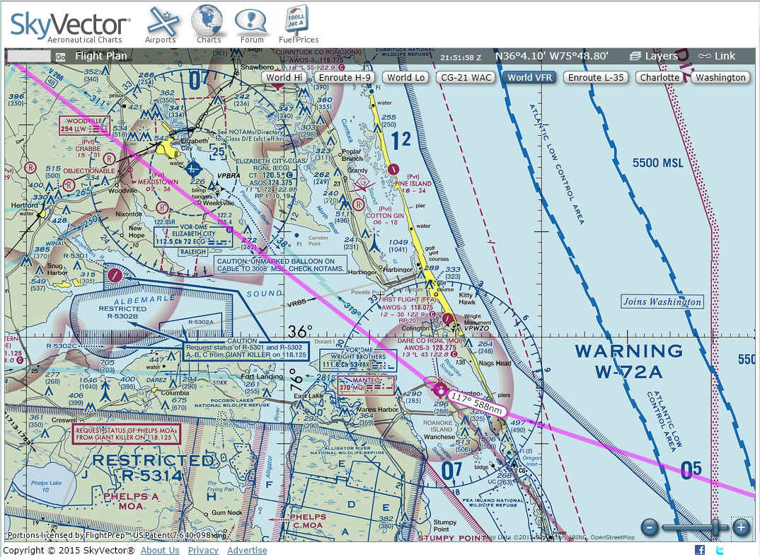
Here is the way an aviation chart appears for this area of North
Carolina showing the Dare County Regional Airport.
Pilots call this a sectional chart. Jerrie's course is the pink
line I entered on the Sky Vector web site for this chart.
The RESTRICTED areas are used by US military aircraft from land bases and from aircraft
carriers at sea. The PINK LINE is her route from Columbus to here, and it
continues 588 nautical miles to Bermuda on a 117-degree course. That
distance is just over 676 statute miles we use in the odometer of our land
vehicles.
She tuned in the low-frequency NDB radio transmitter located at Bermuda as she crossed the barrier island that leads down to Cape Hatteras, North Carolina. These NDB signals can have enough power to travel hundreds of miles, especially over the ocean. She noticed that the TWO automatic direction finder receivers (ADF) in her airplane did not have the same calibration when tuned to the same NDB frequency. She thought this might have been the result of a change to one of the ADF antennas during the large fuel tank installation in Wichita the week before the flight. She decided to use ONLY the one ADF receiver with the antenna she knew had not been bothered during the work done in Wichita. The ADF bearing on that receiver was close to the magnetic compass heading for her course to Bermuda. She would later confirm the magnetic compass had a 10-degree error when flying EAST.
When she got to Bermuda, she was a few miles north of the islands. The
winds across the airport were gusting pretty hard and it was difficult to taxi the
airplane to the terminal after she landed. This can be a big problem for a
tail-wheel airplane like the one she was flying. The brakes were worn down badly as
a result of trying to keep the airplane straight on the ground with the cross wind trying
to turn it into the wind. Runway 30 was the runway where she landed based on her
description of the approach over the water. She did not mention which runway she
used, but did mention having to taxi a long way before she turned on the cross-wind runway
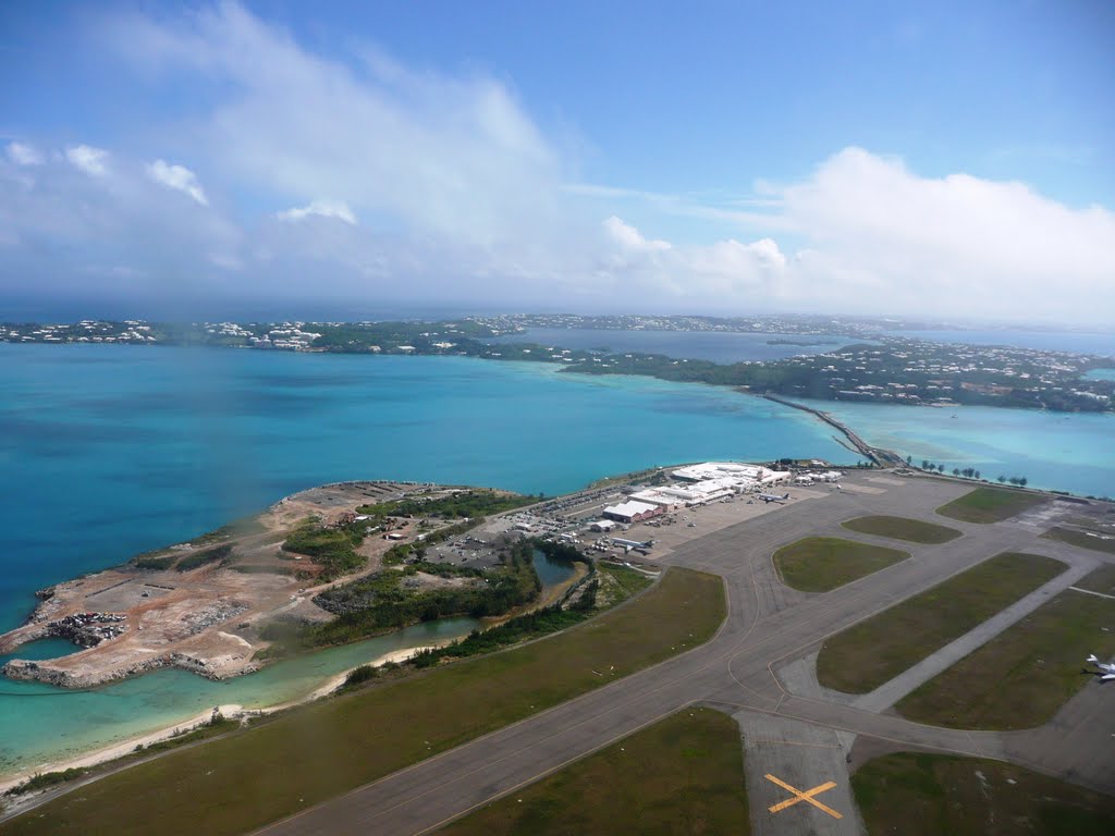
toward the terminal building. This is probably what she saw on the final approach to
the runway. The shoreline is seen at the bottom of the image.
Using this image and the Google Earth measuring tool, I verified she had to
taxi just over 2 miles to get to the terminal building shown as white buildings near
the left side of this "photo". It also shows how the runway is close
to the water at both ends. (Google Earth uses both aerial photographs and satellite
images of our planet.)
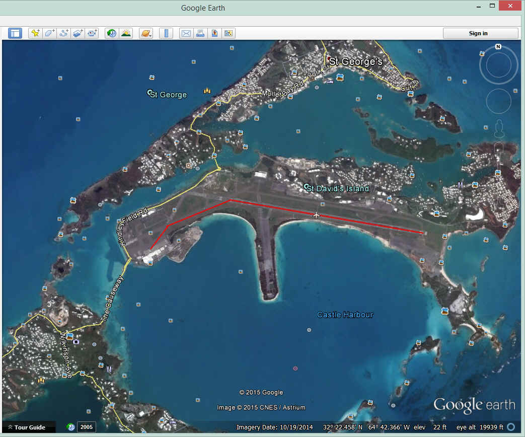
This aerial photo below is looking south showing the terminal and the access
road to the airport. It also shows part of what probably was a short cross-wind
runway in 1964. The numbers at the ends of the runway and the touch down markers are
not there anymore as it is used as a taxiway today.
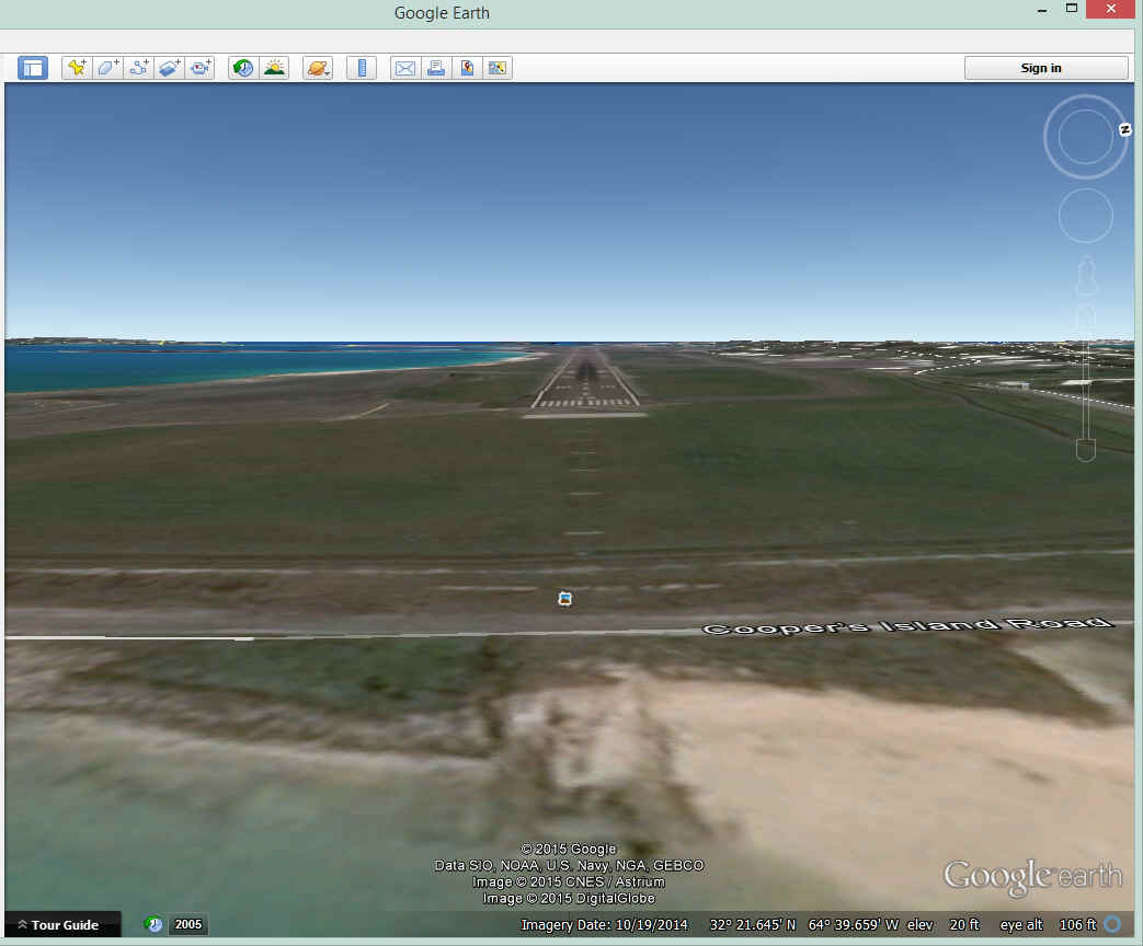
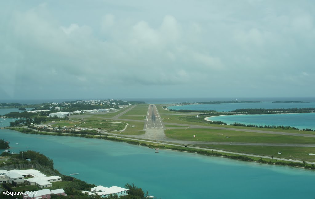
When the winds blow from the west, pilots will use runway 12 (the other end of
runway 30) for landing as seen in this photo. Runway numbers are assigned to match
the nearest 10 degrees of magnetic alignment with the runway. In this case, runway
12 could have a magnetic alignment between 105 degrees and 114 degrees. The other
end of the runway has the number 30 on it since the alignment from that end is 180 degrees
different. Valid runway numbers are from 1 to 36 world-wide. As the magnetic
variance changes on the planet, runway numbers will change to meet the requirements
described in this paragraph. For those of you who are not pilots, this really is a
simple concept that affects not only pilots, but surveyors, ships captains, and even
hikers out on an adventure.
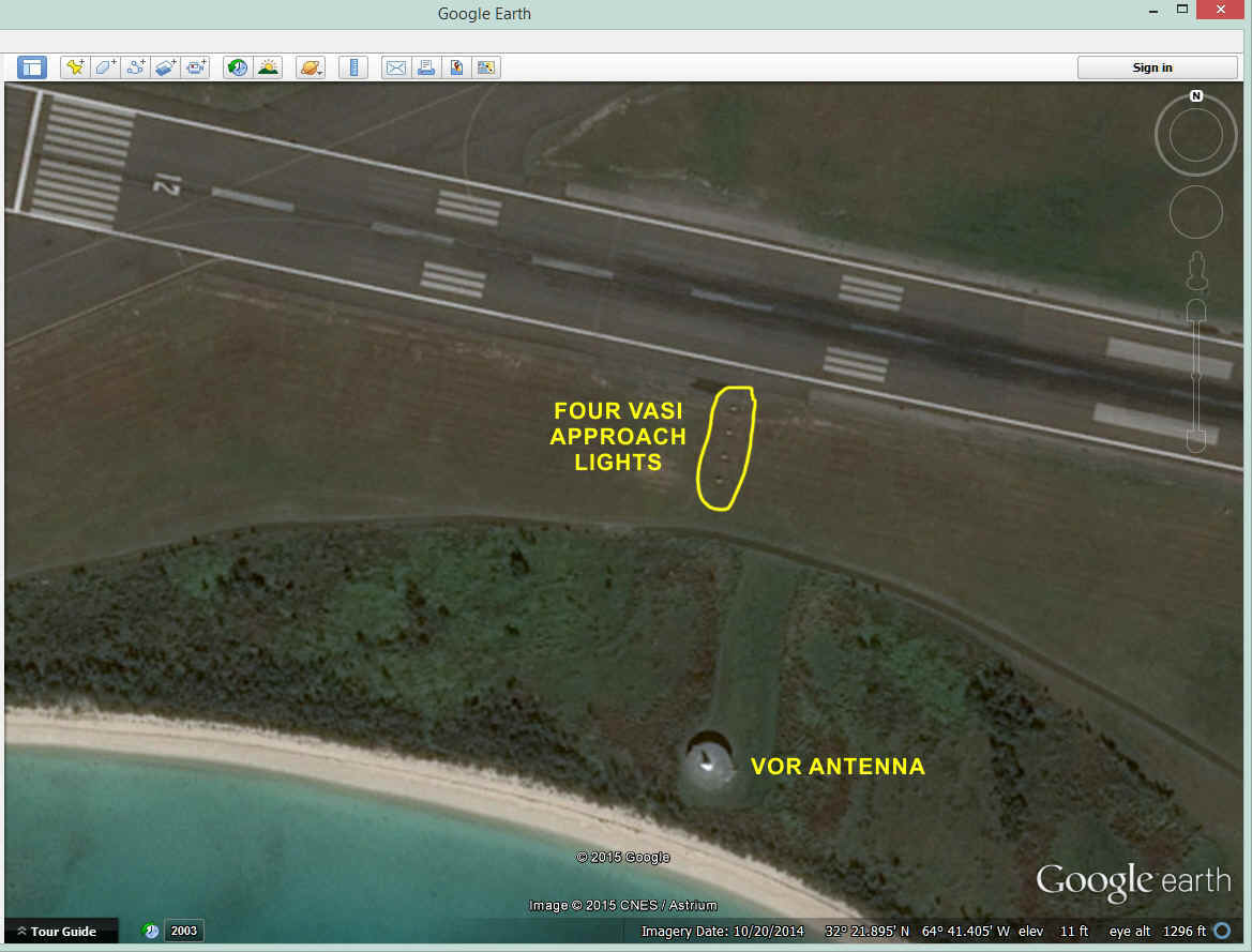
This Google Earth image below shows the end of runway 12, the visual approach
slope indicator lights ( VASI ), and the VHF Omni Range (VOR) antenna on the field at
Bermuda. The VASI lights show the pilot on approach the vertical alignment for the
correct descent angle to the runway. The four lights seen here appear as RED or
WHITE as seen by the pilot. RED is too low and WHITE is too high for the correct
approach to a landing. Each light has a slightly different vertical alignment to
show a RED or WHITE color based on the viewing angle from the airplane. When there
are FOUR VASI lights, the pilot adjusts the approach angle of the aircraft to show TWO
lights as RED and TWO lights as WHITE. This is also known as being "on glide
slope", which is a term used for proper runway alignment when performing an
instrument approach using ILS equipment on the airplane and on the ground. The
airport at Bermuda does not have ILS equipment installed.
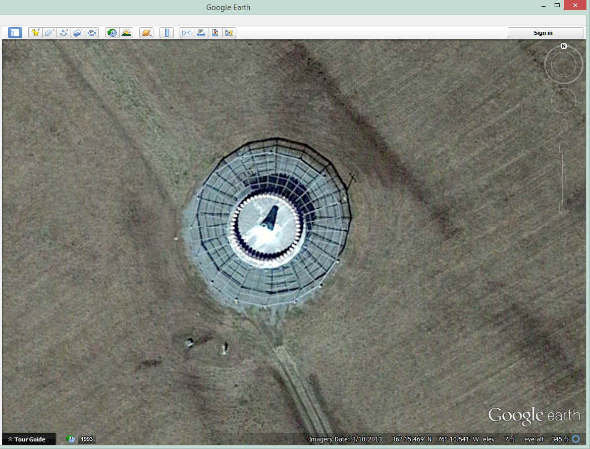
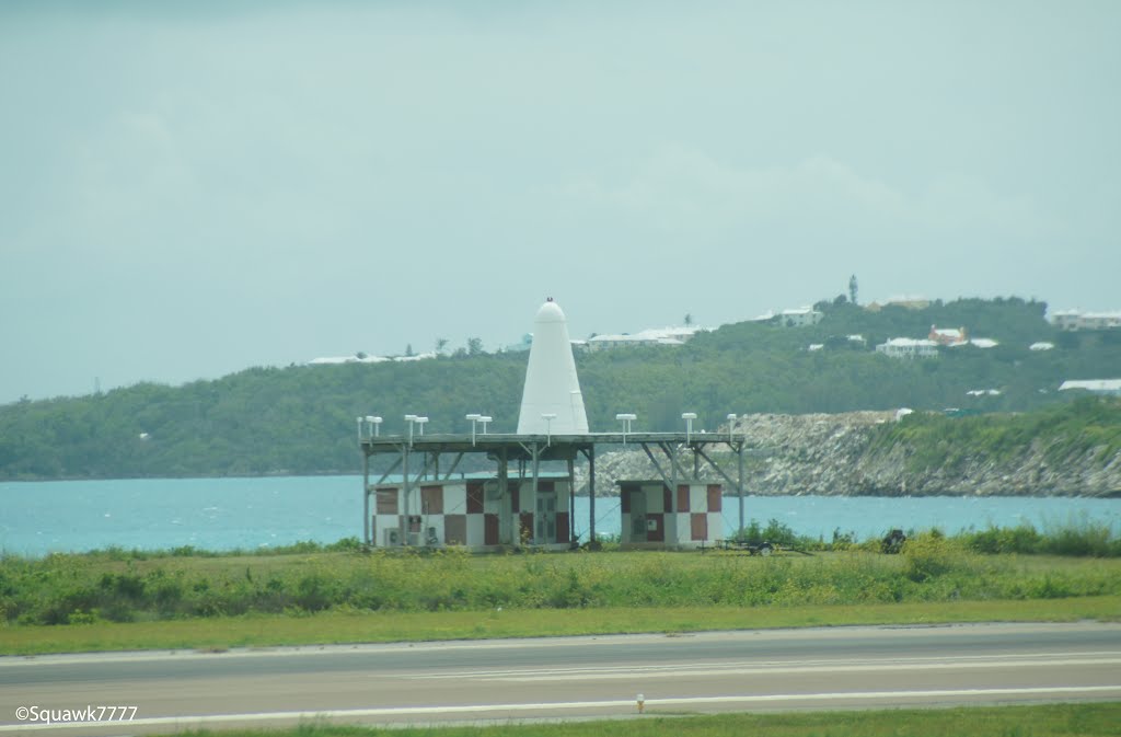
This particular VOR is a terminal area homing beacon. A VOR receiver in
the airplane can display the magnetic bearing TO or FROM a VOR transmitter like this one.
There is a rotating antenna inside the cone. As the antenna inside rotates,
the radio signal it transmits is modulated differently depending on its alignment with
MAGNETIC NORTH. The signal is calibrated to agree with the magnetic compass inside
the airplane when a pilot is homing in on the beacon with his VOR receiver. A
long-range VORTAC has a different configuration from the one seen here. If you look
at the bottom left corner of this photo, you will see this photo was taken by "Squawk
7777". That is the radar transponder code used by "DOD interceptor
aircraft on active air defense missions and operating without ATC clearance in accordance
with FAA Order 7610.4 (USA)". That information comes from Wikipedia. I
would bet Squawk 7777 is the "handle" for a USAF fighter pilot or helicopter
pilot who posted these photos to be seen by users of Google Earth. Based on the
other photos in his collection, he was probably working as an airline pilot when he took
this photo and others in his collection.
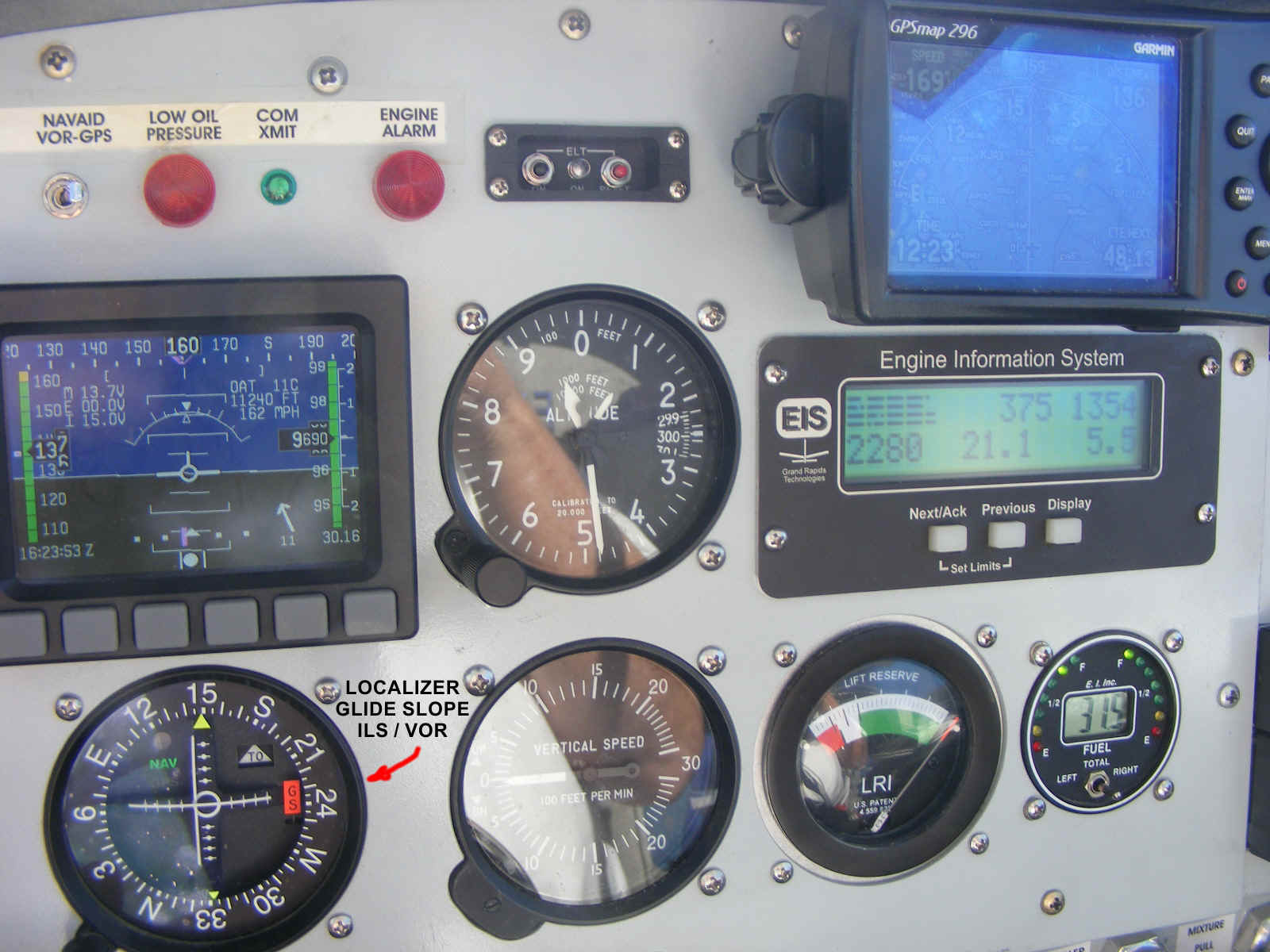
Inside the airplane, a pilot with equipment for an ILS approach to a landing has an indicator on the instrument panel like the one at the bottom LEFT of the photo below. The device has one VERTICAL white indicator bar that moves LEFT or RIGHT to show if you are aligned with the runway centerline. The HORIZONTAL white indicator bar moves UP or DOWN to show if you are ABOVE or BELOW the proper GLIDE SLOPE ANGLE to make a safe landing. The pilot maneuvers his airplane to keep BOTH indicators in the center of this device. The particular device here is a GI-106 resolver connected to my Garmin AT SL-30 NAV/COM radio. That radio can receive VOR or ILS signals on the NAV receiver, and the COM portion of the receiver can transmit and receive voice communications with air traffic controllers and other airplanes as needed.
The information on this panel confirms my airplane was flying at approximately
9,500 feet above sea level, while cruising at 162 MPH true air speed on a magnetic heading
of 160 degrees with an 11 MPH tail wind. The GPS reports a ground speed of 169 MPH
and the airplane is in level flight from the vertical speed indicator reading near ZERO
feet per minute, with wings also level as seen on the color display. The NAVAID
auto-pilot (not shown) is keeping the airplane on a course that is programmed into the
Garmin GPS 296 receiver. The next waypoint on the GPS is 136 miles ahead and the
airplane should arrive there 48 minutes after this photo was taken. As I read
Jerrie's book, she talked about having to do the math to estimate arrival times at her
waypoints, verify her course using a radio navigation receiver and a compass, and she had
to trust the weather briefing to give her winds aloft to get an idea of how long she would
have to fly to reach her waypoints. The modern equipment here does all that work for
you and you will always find your destination within just a few feet, not miles off course
like she did arriving at Bermuda.
Jerrie had the H.F. radio power connection fixed in Bermuda. The fuel
tanks had to be removed from the cabin to gain access to the battery where the H.F. radio
power cable was found to be not attached. The battery for the Cessna 180 is behind
the baggage compartment to balance some of the weight of the six-cylinder engine up
front. The top of that smaller forward fuel tank served as a chart table,
etc. She waited several days in Bermuda for the weather in the Atlantic Ocean to
clear before the 2,256-mile flight to Santa Maria in the Azores islands.
| CLICK HERE for PAGE 3 | CLICK for Jerrie Mock MENU | Return to N2PRISE MAIN MENU |