Fiber Optic Fundamentals - PAGE 3.
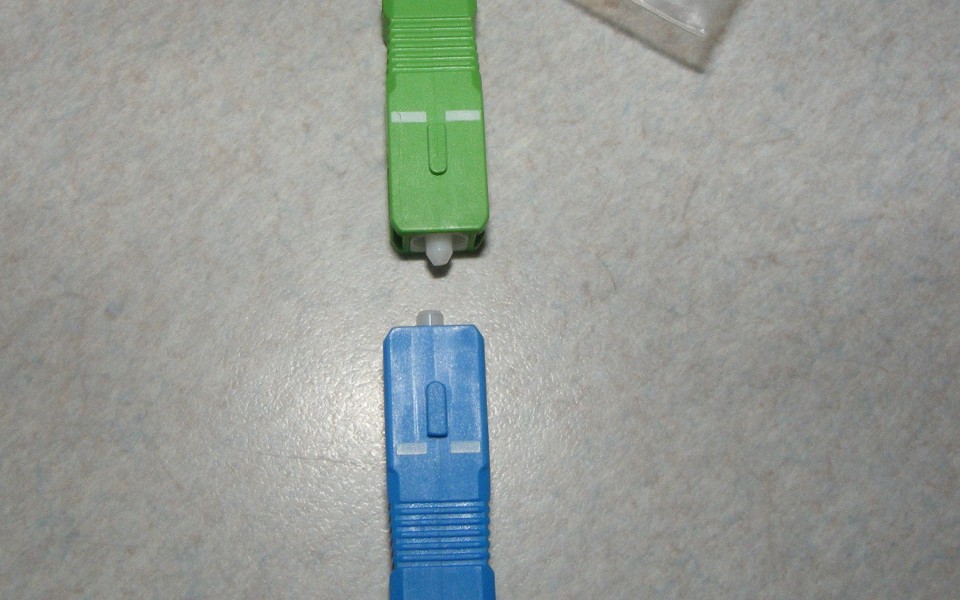
ONLY ONE type of fiber is used in broadband RF fiber optic networks: Single-mode fiber with GREEN angle-polished connectors! The 82-degree polished face with respect to the fiber path is clearly visible on the green connector in this photo. The BLUE or BLACK, 90-degree polished flat-finished connectors are only used in DATA networks sending binary signals ONLY. Those networks send telephone and computer network signals all around the world. The DATA can be regenerated again and again. With broadband RF, the signals can not be regenerated. That is why we use only the best connectors with -60 dB reflectance of the laser light.
Fiber Optic Reflections Degrade RF Television Signal Performance
Watch this video
that compares the RF performance of a fiber path with FLAT ends on fiber connectors
AGAINST the better performance with GREEN angle-polished
connectors. The noise
floor of the fiber path is seen on an RF spectrum analyzer in the video with a
20 dB change in the demonstration. That 20 dB difference reduces the
carrier-to-noise (C/N) of all the RF signals. NTSC ANALOG channels will
get "snowy or fuzzy." Digital QAM high-definition TV signals may
not work or have "tiles or blocks" on the TV screen.
There is a simple demonstration that can be done at home to understand reflection inside optical fibers with FLAT ends on the fiber connectors. Most folks have a big mirror in the bath area. If you also have a smaller make-up mirror or a hand mirror, you can make this observation. Stand in front of the large mirror with the smaller mirror in your hand. Point the FLAT reflecting side of the small mirror toward the bigger mirror and raise the hand mirror close to your face. Look in the LARGE mirror at the reflection of the small mirror in your hand. Adjust the smaller mirror to the angle that lets you LOOK into the smaller mirror to see it several layers DEEP. Your eyes will need to be just above the small mirror to see deeper into the multiple reflections. You will notice how the multiple images get smaller based on the distance between the two mirrors. You will also see a "worm hole" effect as you adjust the mirror in your hand. Each smaller image gets darker because of the number of times the light bounces back and forth between the mirrors. Each mirror does not reflect ALL the light.
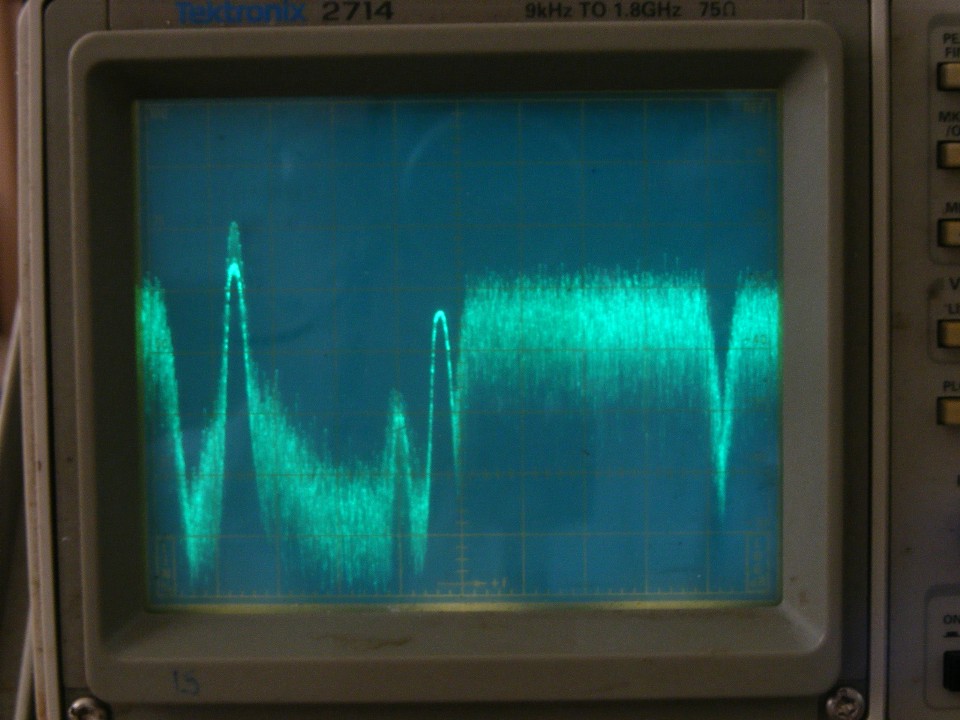
We have talked about the correct RF levels needed to achieve the proper optical modulation index with NTSC analog and QAM television signals. Yes, the big cable companies talk about getting "Digital Cable" for more channels. You need to understand what they are talking about. It is the processing of the various MPEG video digital bit streams at the headend and again inside that "cable box" that provides all those channels to your television set. The processing of those signals at the headend results in an RF carrier with up to 256 possibilities of phase-angle and RF amplitude modulation on a carrier wave that fits in ONE 6 MHz television channel here in the USA. It looks like a haystack on an RF spectrum analyzer. It is an RF analog-modulation format that represents a serial digital bit stream containing several video signals viewable after the "cable box" decodes those bit streams for your TV set. The three signals on the left side of the spectrum analyzer display below make up ONE analog NTSC color television channel. The "fuzzy haystack" QAM 256 signal is on the right side of the display screen. It can have TWO high-definition channels on it, or up to 13 standard definition video channels on a Comcast Cable system like the one in Chattanooga where I took this photo. Trying to compress more standard definition channels leads to lower picture quality. QAM signals can also carry high-speed data signals for internet connections.
ALL RF SIGNALS ARE ANALOG by nature, EXCEPT for the ham operator sending MORSE CODE, which is a signal that is being turned OFF and ON as a series of "dots and dashes" to send a message. All other RF signals are modulated in amplitude (AM), frequency-modulated (FM), phase-modulated (PM), or a combination of those methods (8VSB, ASK, PESKY, QAM).
RULE 1: Lasers perform best when the RF signals applied to the laser are of EQUAL STRENGTHS based on the types of signals being transmitted. The number of RF signals being transmitted determines the correct RF input level to the transmitter.
For many years since "digital cable TV" channels were introduced,
CATV systems learned that the NTSC channels were the most sensitive to RF signal
distortions compared to the performance of QAM signals. The signal levels for the
NTSC channels were combined in the headend to have EQUAL RF levels before sending them
into the fiber optic laser transmitters. The QAM signals for QAM 64 were set at 10
dB lower than the NTSC channels. When QAM 256 became the standard method for
transmitting digital TV channels, those signals were set to be only 6 dB lower than the
NTSC channels. More and more cable systems are becoming ALL QAM 256 digital
systems. The only NTSC channels that remain are used to control RF automatic gain
control in the AMPLIFIERS of the coaxial cable plant going to customer homes.
Those few NTSC channels are still operated (usually without video or sound) at their
"normal" signal level 6 dB stronger than the QAM signals. CATV technicians
use them as a quick reference during system installation, and checking line amplifiers.
Using a digital RF signal level meter to monitor a QAM 256 channel, the
constellation of ANALOG amplitude and phase-modulated data points can be displayed.
A normal distribution of the signal vectors looks like the graphic image seen below.
If you tried to put a QAM signal in channel 2 from 54 MHz to 60 MHz, the group delay of
two-way diplex filters in the RF amplifiers would distort the patterns of dots to the
point where they may fall outside the boxes below and the channel would develop
"tiling" or a "blocky" image that jerks or fails completely.
Each box below represents a number from Zero to 255 in decimal numbers or 00 to FF in
hexadecimal computer code. All those 256 possibilities are the result of converting
television signals to a digital bit stream of numbers representing MPEG encoded and
compressed data that can be restored as high-definition or standard definition TV
pictures. Cable modem internet service can also be transmitted as a QAM-256 RF
signal. The "Constellation" depicted below has 16 boxes across and 16
boxes vertical for 256 numeric values. This is graphical depiction seen on CATV
signal level meters that are compatible with DIGITAL QAM RF carriers.
The use of fiber optic RF transmitters for SATELLITE LNB RF signals is common
since the RF attenuation of coaxial cable can be a problem for signals above 1,000 MHz.
Fiber optic links that transmit satellite and other signals from 250 MHz to over
4,000 MHz (4 GHz) avoid the coaxial cable loss issues. The cable from the satellite
antenna should be as short as possible before reaching the fiber optic transmitter.
As with CATV signals, the satellite LNB signals should be kept EQUAL as much as
possible. The photo below shows the RF output of an MFH-1 frequency stacker for
Direct TV signals used a few years ago. Each signal below is ONE satellite
transponder that may have one or more digital video streams encoded in the modulation.
Notice how they resemble the QAM signals seen in the photo above. The display
below has some video filtering on the trace to minimize background noise, thus making the
individual transponders better defined.
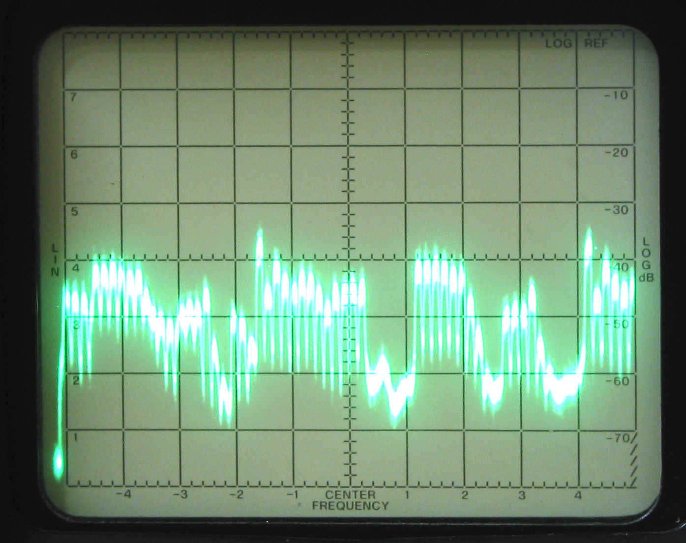
The RF signals from Direct TV legacy antennas can be THREE 500 MHz wide blocks of spectrum. Those bands of signals exist from 250 MHz to 750 MHz, 950 MHz to 1,450 MHz, and 1,550 MHz to 2,050 MHz. Those three bands can appear on all FOUR RF outputs from a legacy antenna when polarity lockers are used ahead of fiber optic transmitters. A multi-switch or Direct TV satellite receiver usually powers their parabolic antennas. The voltage provided to the antenna feed system can be 13 volts DC, 17 volts DC, and the presence of a 22 kHz square wave voltage which can also be present on those DC voltages giving four possible output signal groups from the multi-switch embedded in the antenna feed horn assembly. The result is a method to control which satellite polarity is presented to the multi-switch or receivers. Since no voltage can be sent via glass fiber, use of a polarity locker to produce those voltage combinations is required ahead of a satellite fiber optic link.
RULE 2: Fiber management is part of the second rule where the laser power of the transmitter is matched to the loss of the fiber path.
There is only ONE choice of optical connectors for analog fiber systems: angle-polished GREEN connectors. There are three types of these angle-polished connectors to choose from: SC-APC, FC-APC, and the smaller GREEN LC-APC. The second part of rule 2 is to match the power of the fiber transmitter to the loss of the fiber optics including any optical passive devices, and patch bay losses from extra fiber jumpers.
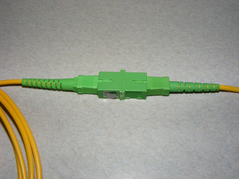
The SC-APC connectors are made using GREEN rectangular plastic material around
a ceramic core which precisely aligns the fiber ends in the center of the mating bulkhead
connectors used on optical transmitters, receivers, splitters, and multiplexers or
de-multiplexers (MUX and DEMUX). The bulkhead connectors are a precision empty pipe
with a mechanism that provides an audible CLICK when a male connector is inserted.
When the matching connectors are plugged into both sides, there is a slight pressure that
is applied by the clicking tab on the connectors. The small space at the end of the
key slots seen below shows this slight pressure on the faces of the mated connectors.
ALL SC-type connectors have a key tab that allows them to fit in ONLY ONE
position.
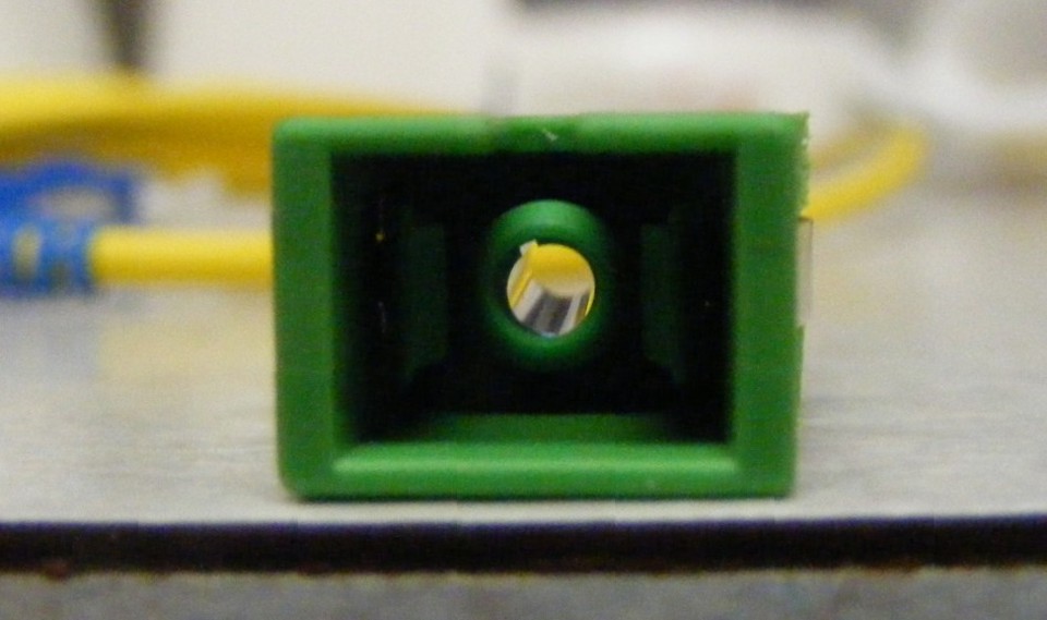
![]() March 23, 2016: Bulkhead connectors have an
empty metal sleeve inside the receptacle. That sleeve creates the precision
alignment of the ceramic ferrule of two similar SC-type connectors. The metal sleeve
seen in this photo is the only force acting on the two male connectors to align their
fiber cores when they are plugged into this bulkhead connector. The fiber cores are
less than 9 microns in diameter. Only a precise alignment works here. A pair
of clean SC-APC connectors have a typical insertion loss of 0.2 dB.
March 23, 2016: Bulkhead connectors have an
empty metal sleeve inside the receptacle. That sleeve creates the precision
alignment of the ceramic ferrule of two similar SC-type connectors. The metal sleeve
seen in this photo is the only force acting on the two male connectors to align their
fiber cores when they are plugged into this bulkhead connector. The fiber cores are
less than 9 microns in diameter. Only a precise alignment works here. A pair
of clean SC-APC connectors have a typical insertion loss of 0.2 dB.
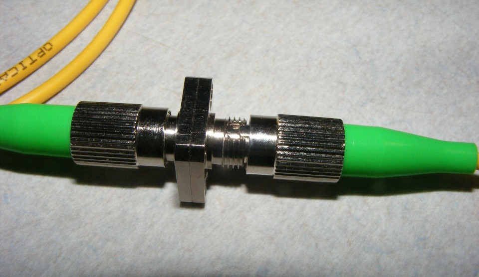
The FC-APC connectors seen below have a metal body with a key-tab so they fit
in their matching bulkhead connectors in only one position. The outer part of the
connector screws onto the bulkhead connector. There is a GREEN strain relief rubber
or plastic marker around the fiber at the connector to indicate the angle-polished faces
of these connectors. These connectors MAY NOT always align the fiber cores as
accurately as an SC-APC connector. It is the outer ring that can cause the
misalignment when it is tightened too much. Look closely at the slot in the
threaded part of the bulkhead connector. The KEY does not exactly fill the
slot. Too much pressure from twisting these threaded rings can force the two faces
of the connectors out of alignment. I have personally measured as much as 2.5 dB of
loss from this effect instead of 0.2 dB for a clean SC-APC pair of connectors with good
geometry at the face of the connectors. Sometimes fiber is not perfectly centered in
the ceramic connector face. I have seen some of those bad connectors on one of my
installations. They can be identified through a fiber microscope by rotating the
fiber connector while observing the face of the connector. The gray portion at the
center of the connector surface should remain centered in the view as the fiber connector
is twisted in the connector adapter on the microscope.
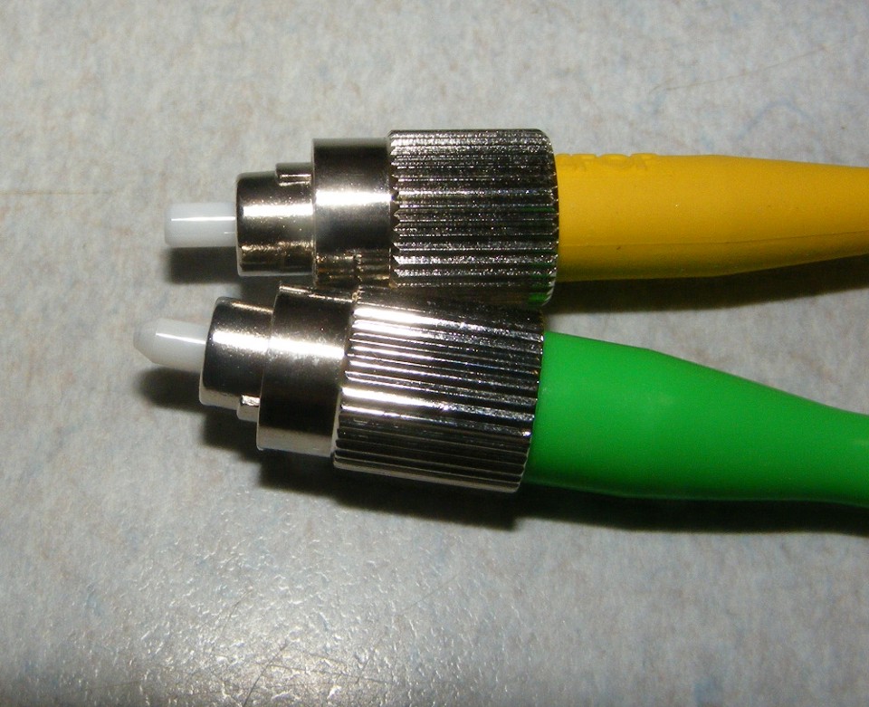
The FLAT-finished FC-PC or FC-APC connectors will have a YELLOW, BLACK or BLUE
strain relief.
The GREEN LC-APC connectors are about half the size of the SC-APC connectors and are great for saving space in multi-connector patch bays. They have the audible CLICK feature as well. These miniature connectors also come in BLUE LC-PC and LC-UPC varieties used in data networks and are NOT usable in analog RF fiber optic networks.
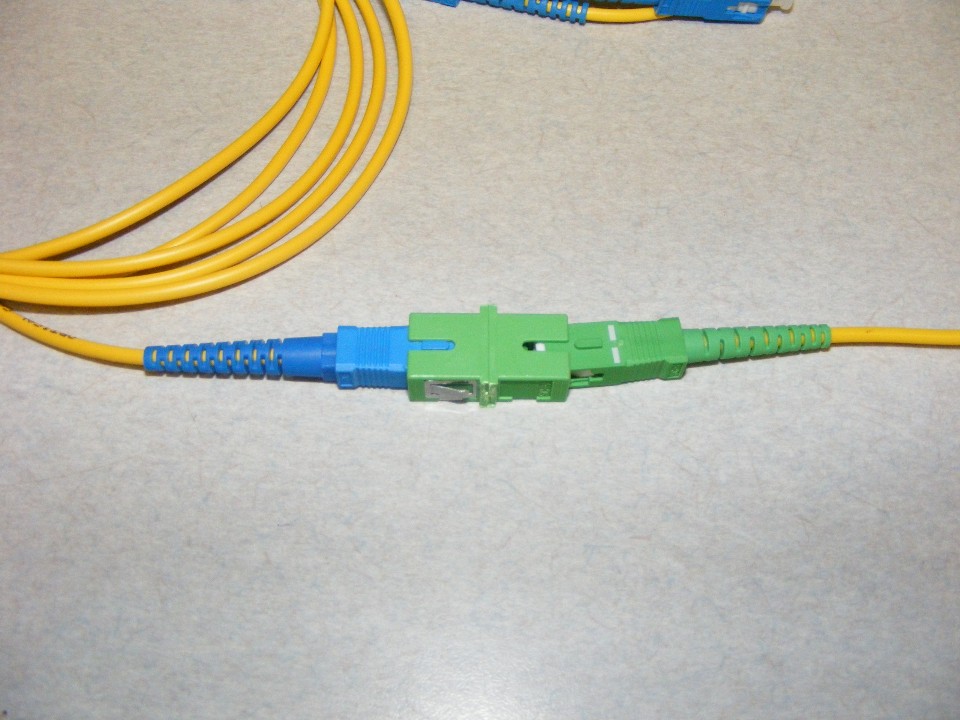
Be careful of the BLUE SC-PC and SC-UPC connectors. They are exactly the
same size and shape as the GREEN SC-APC connectors RF signals require. If you plug a
GREEN MALE connector into a BLUE bulkhead FEMALE connector, there is probably a BLUE
connector on the other side, and that spells trouble! The GREEN bulkhead connector
is an indicator of an angle-polished connector on the other side when you cannot see it as
it is shown here. This photo is shown with the second connector NOT engaged since
the face of both connectors could be damaged. IF they were clicked in position and
did not fracture the ceramic ferrule, the fiber would still not touch, providing from 5 to
10 dB of optical loss, and a reflection of the laser light. That optical loss would
cause a loss of analog RF signals of 10 to 20 dB below normal RF signal levels from the
optical receiver.
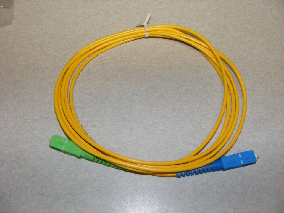
With that last paragraph, someone out there is thinking if I get a fiber jumper
cable with a GREEN connector on one end and BLUE connector on the other end to mate with
another BLUE connector, it should work, RIGHT? WRONG,
unless of course you are transmitting a DIGITAL DATA fiber optic signal that blinks the
laser on and off. The RULE for analog RF transmissions over single-mode fiber is
SIMPLE: NO FLAT CONNECTORS can be anywhere in the path from
transmitter to receiver! ONLY Use GREEN SC-APC connectors on fiber pigtails
that are fusion-spliced to long fibers, EVERYWHERE in the fiber paths! No field-installable connectors or matching GEL allowed! When
the matching GEL dries out, you have cleaved, flat fiber ends and reflections as if you
had used BLUE or BLACK connectors.
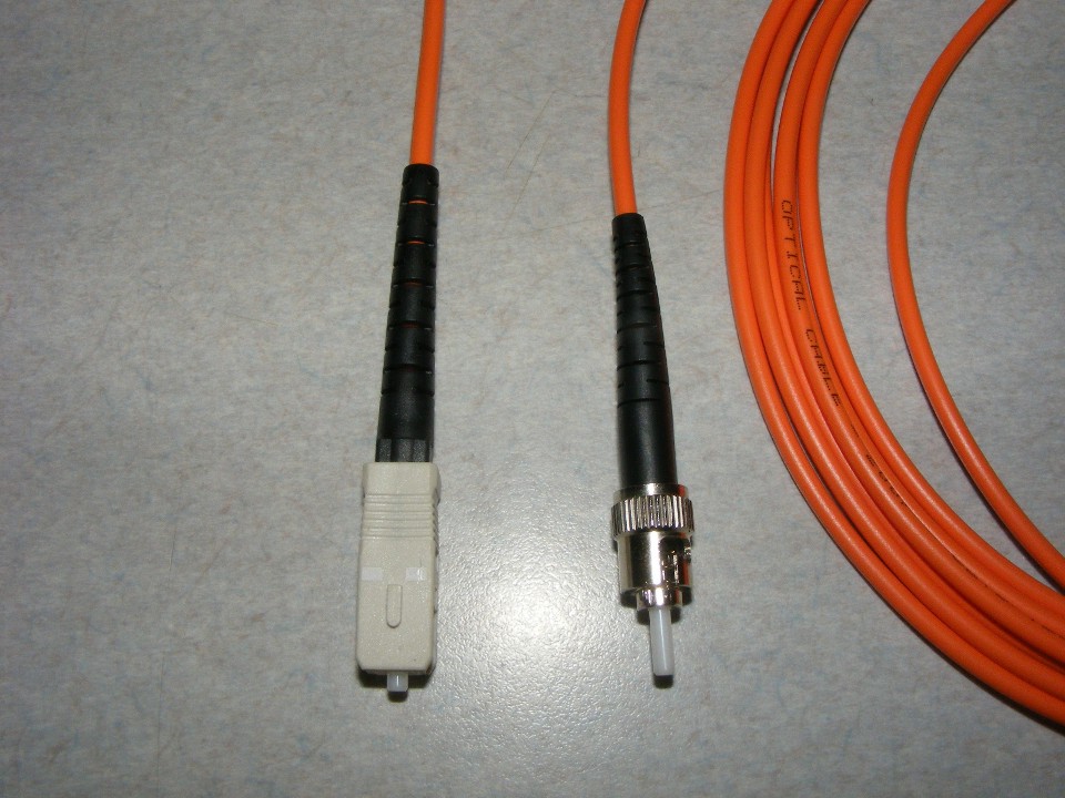
IF you see a WHITE or GRAY SC-connector, those are used in MULTI-MODE fiber
installations and have no place in analog RF over fiber networks. The ORANGE jacket
on the fiber is also a sign of MULTI-MODE fiber. The connector on the right is an ST
connector which has a twist locking mechanism with a spring inside to insure a solid fit
with the matching ST connector. ST connectors have a longer white ceramic ferrule
and a flat finish at the end. They also have a key to fit a slot in the matching ST
bulkhead connector.
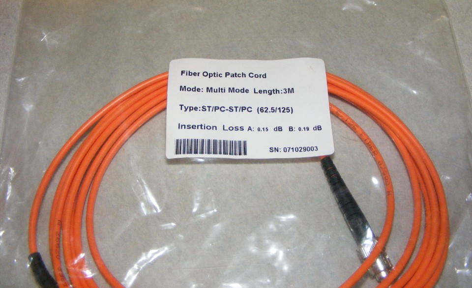
The label on this bag indicates this fiber optic patch cord is an ST/PC on both
ends, Multi Mode fiber, 3 meters in length, and has a 62.5-micron core with the normal
125-micron cladding to keep the light inside the core. Between the actual fiber and
the orange outer jacket is a woven armor sheath made of Kevlar material.
| Fiber Fundamentals - PAGE 4 | RETURN to TECHNICAL ARTICLES MENU |
This page was updated on May 12, 2016.