Fiber Optic Fundamentals - PAGE
1.
Fiber optics can challenge the first-timer to this part of analog RF signal
distribution. There are some fundamentals from "the
amplifier sweet spot article" that apply to getting analog RF signals onto fiber
optic links and retrieving them as usable signals at the other end of the fiber. In
these pages we will discuss the correct type of fiber and connectors required, the proper
RF input signal levels to the fiber optic transmitters, and optimizing the fiber-to-RF
conversion at the optical receiver with the correct received optical input power. If
you were paying attention, that breaks down to three simple rules:
1. Provide the correct RF input signal level to the fiber transmitter.
2. Match the transmitter laser power to the loss of the passive optics, fiber
connectors at bulkheads, and the loss of the fiber over the path.
3. Arrive at the optical receivers with the correct optical input power level.
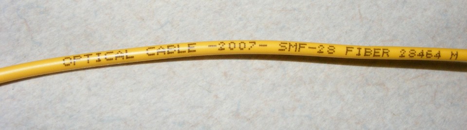
Transmission of wideband analog RF signals is only possible over single-mode
fiber (SMF-28) that has a 9-micron core diameter. Another code name for single-mode
fiber is G652. It depends on who made the fiber. If you have fiber jumpers
that are G657, the "bend insensitive fiber" in your installation, you will find
that our OTOA-1000 fiber optic attenuator will not work. This photo shows three
different size fiber loops that attenuate the 1310 nm wavelength from 1 dB to 7 dB
depending on how many of the circles are used. The largest of the three circles will
attenuate the 1310 nm laser signal about 1 dB. The middle loop will attenuate 2 dB.
The smallest circle attenuates approximately 4 dB. This photo shows a
configuration for 5 dB total attenuation. The online data sheet for this
product is
found here:
http://www.olson-technology.com/ds/OTOA-1000_Rev.C.pdf
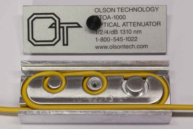
The OTOA-1000 is not usable for 1550 nm signals. The loss of the largest
of the three circles and the "race track" strain-relief loop has a
loss of nearly 6.5 dB at 1550 nm. That same fiber configuration for 1310
nm is about 1 dB loss for SMF-28 fiber.
The majority of fiber installations use 1310 nm transmitters that do not work
with "dispersion-shifted fiber" that is optimized for 1550 nm wavelengths.
SMF-28 and G652 fiber have ZERO dispersion time-delay distortions at 1310 nm ONLY.
MULTI-MODE fiber will not work since the core diameter for that fiber is either
50 microns or 62.5 microns. The problem with the larger core diameters of MULTI MODE
FIBER is the reflection of the light rays bouncing off the side walls of the core, while
some rays of light go straight down the core without the zigzag path off the walls.
The effect of this causes the received light to no longer be "coherent" at the
end of the fiber. Multi-mode fiber is used in short lengths up to about 1000 feet,
and only for digital fiber signals where the laser blinks on and off representing binary
ones and zeroes. Digital signals can be regenerated at every receive point with
virtually no loss in the data. Analog RF signals cannot be regenerated. It is
important everything be done the correct way with RF signals over single-mode fiber optic
links.
With single-mode fiber, the smaller core diameter keeps the rays of light
coherent for greater distances. Transmission paths can reach many miles depending on
the wavelength of the laser light transmitted. For now we will discuss only 1310
nanometer wavelength signals (1310nm). Other wavelengths can have slightly different
fiber issues for those specialized networks.
Since these technical articles are about CATV applications, we will start with
forward path, broadband CATV fiber optic transmitters. Many laser transmitters for
converting wideband analog CATV signals to a light wave utilize "Butterfly"
distributed feedback (DFB) lasers for optical power output levels from +8 dBm to +15
dBm. They have good RF linearity for CATV signals to minimize the unwanted RF
distortions known as composite-triple-beats (CTB) a third-order distortion which is
visible as lines in the pictures or a busy background. Composite second-order (CSO)
distortions are also reduced. Poor carrier-to-noise (C/N) or noisy pictures occur when RF
input signal levels are too low to overcome the noise figure of any active RF amplifier
device. Lower-powered coaxial DFB lasers also have good performance for satellite
L-Band applications.
Inside the fiber optic transmitter chassis, the first RF amplifier stages
provide a broadband impedance match for the CATV signals transmitted to the laser
device. The laser has a lower impedance than the 75-ohm coaxial cables of the
network. The RF input circuitry handles that impedance transformation of the signals
going to the laser itself. The laser works best with RF signals that are of EQUAL
signal strength to each other. Depending on the design and gain of the RF input
circuitry, each manufacturer will provide a technical manual indicating the optimum RF
input level for their transmitter. The actual RF level can vary based on the number
of analog and digital QAM-modulated channels. QAM signals are commonly set 6 dB
lower than analog channels. This is done since the QAM signals do not need the same C/N
performance required for analog NTSC television channels. The same "Sweet
Spot" rules apply to any active RF device for optimum performance. This is the
usual balancing act of C/N vs. CTB that occurs with any broadband analog RF amplifier
device. You can also think of these as the "Goldilocks Rules", not too
hot, not too cold, always just right. This is the heart of RULE number 1 seen above
on this page.
When discussing RF signals levels in CATV networks, the measurements are
usually referenced to 1 millivolt of signal, which is 0 dBmV. Optical power levels
in fiber are measured in reference to 1 milliwatt, or 0 dBm. The world of 50-ohm RF
transmitters and receivers also uses the milliwatt (dBm) or 1-WATT referenced
measurements (dBW).