WINTER 2012 · · PAGE 356.
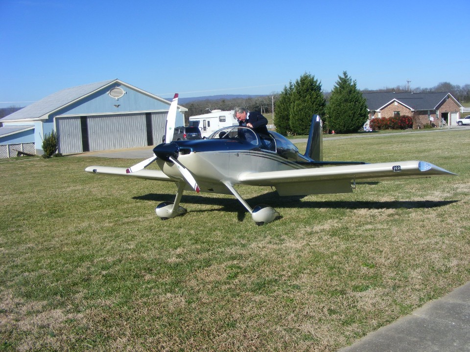
December 31, 2011: It is
the last day of the year and a Saturday, which means a visit to the Folks Field
airport. The visiting pilot today is Henry Hodgkins with his RV-7 completed in May
2011. He lives in Calhoun, Georgia.
January 9, 2012: The photo below is a peek into my life in the 1980's. The photo shows an old Microdyne model 1100-CSR satellite television receiver built by that company when I worked there from 1978 to 1989. I found this one in a junk pile of a cable TV repair shop in Alabama a few months ago. It had power supply problems as I could see it had suffered from heat-related issues. I wanted it because of the history I had with this model. I knew the guy who designed it and I recognized the initials DB from the QC test technician Dave Bleem who first tested it.
The dual RF input signals from two low-noise amplifiers (LNA's) on a satellite
dish antenna connected directly to this unit. There is an RF relay at the right rear
of the unit that selects one of two LNA feeds from the antenna for vertical or
horizontal-polarized signals from the geostationary satellite. The tunable
dual-cavity microwave input band pass filter is ahead of the RF tuner on the right side of
this photo. The input frequency range is 3,700 MHz to 4, 200 MHz or 3.7 gigahertz to
4.2 gigahertz (GHz). This receiver was unique since it had one local oscillator that
used the third harmonic in the first mixer stage and the fundamental oscillator frequency
in the second mixer. The 70 MHz intermediate frequency from the tuner RF
output port went to the main I.F. amplifier / demod / video / audio circuit board on the
LEFT side of the photo. That small black cable looped around in the center of the
photo normally connects to the biggest circuit board at that silver spot near the power
supply in the back corner of that board. I needed the SMB connector that was there
to build an interface cable for my RF sweep test equipment. The I.F. bandpass filter
is aligned by those five square silver metal cans on the big board seen to the left of the
three power transformers. There are test points on the input and output of the
filter circuits that allow the isolation and tuning of the I.F. filter with no power
applied to the remainder of the circuits. I plugged my test cables in from my sweep
test equipment and determined the filter was badly aligned by whoever was trying to repair
this unit.
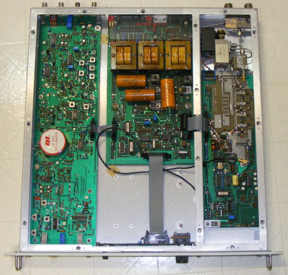
It was a unit like this one that caused a problem with ONE cable television company in rural Maine. The local oscillator from the tuner was leaking out of the unit and interfering with a nearby UHF channel 56 television broadcast signal being received by a cable company near Eastport, Maine. That short gray computer ribbon cable between the power supply board and the RF tuner board was the issue. I modified a unit with feed-through capacitors in the bulkhead between the power supply and the tuner sections. I then used a similar ribbon connector cable that had the wires fanned-out with each wire soldered to one feed-through capacitor and another similar ribbon cable on the inside of the tuner section to complete the DC circuit. This was binary-coded frequency selection data that tells the tuner which satellite transponder to select. The I.F. output goes to a delay-line discriminator in a round shield can under the red and white label to produce the video and audio routed to the output connectors at the left rear of the chassis from the big circuit board. When that ribbon cable modification was completed, the gap in the wall where the original flat ribbon cable crossed the top of the wall was closed using copper adhesive tape. The copper tape and the feedthrough capacitors sealed the RF tuner section. The local oscillator signal no longer leaked out of the receiver. We exchanged the modified receiver with the standard unit that was causing the problem in Maine. No other customers anywhere in the USA had ever reported a similar problem in the years I worked with Microdyne Corporation in Ocala, Florida. I was the answer man for all things to do with satellite receivers and uplinks for the company. This obsolete satellite receiver also provided a 5-volt regulator chip I needed to repair another electronic project for my CATV RF test bench, a Tektronix 2714 spectrum analyzer..
February 5, 2012: It is Sunday and time to update the web site again. Wow, look at the date for the entry above. January was a dull month with nothing much going on. I did change the oil in my airplane and cleaned the spark plugs. When I get back from the current road trip, I will pull the airplane out of the hangar and run the engine to get it warmed up for cylinder compression tests. I will also complete the annual inspection and get the airplane ready to fly again, as I am fit and able again. I have been talking with my doctor to get the last things I need for my FAA medical to be re-instated and get all my flight privileges restored.
I began this road trip on Friday, February 3 and made a stop in Virginia to pick up an optical spectrum analyzer I will need for my work this week in New York City. I spent Friday night at a motel north of Roanoke and headed for Pennsylvania on Saturday morning. The GPS was telling me I was going to arrive at my destination way too early since my son Jason and his family were spending all day at a gymnastic meet where the girls were competing. I punched in the GPS waypoint for the new Air & Space Museum at Dulles Airport and realized I could spend the three extra hours there. I had taken a lot of photos and posted them here on my first visit to the museum. Today, I wanted to see some of the exhibits I missed on my first visit. I also got into one of the guided tours that overlooked the restoration area. They have a twin-engine Sikorsky flying boat that survived the Pearl Harbor attack on December 7, 1941. It should be restored and on display sometime next year. The guide told us of a similar airplane that is still in private service.
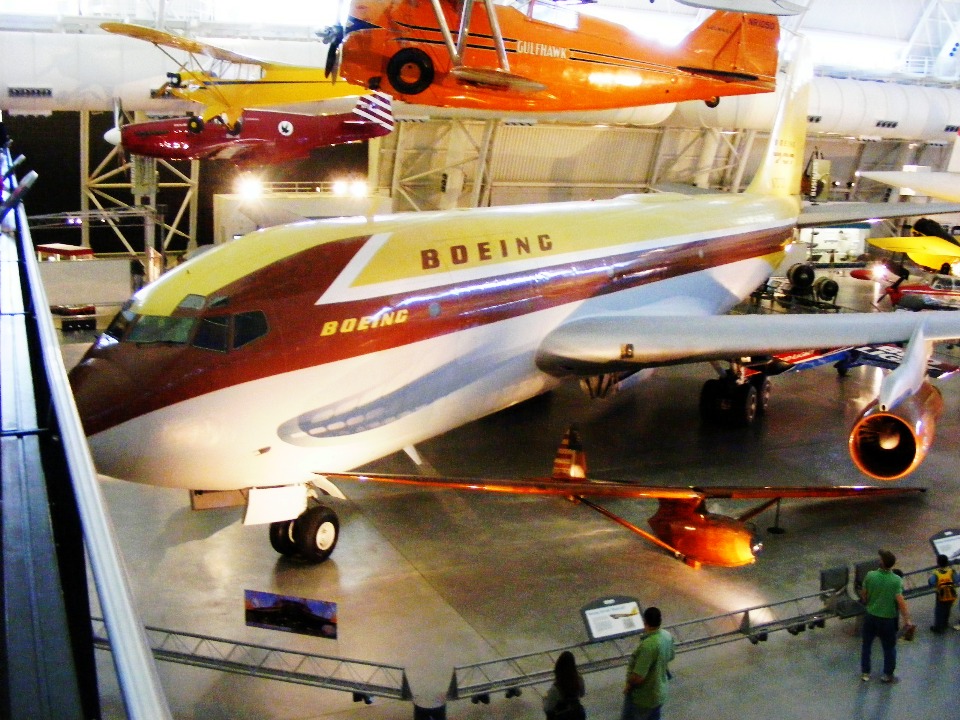
There were three of us pilots talking with the guide after the tour was
completed. We were on the elevated walkway near the commercial airplane
exhibits and the discussion turned to an historic record-setting flight of a single-engine
airplane over the north pole. The airplane was a P-51 Mustang that had been
specially adapted with long-range fuel tanks in the wings instead of the drop tanks used
during World War II. That bright red airplane is hung directly in front of the
elevated walkway above the Boeing factory prototype for the KC-135 and Boeing 707 seen
here.
I mentioned that one of the last single-engine airplanes to fly over the north pole from Canada to Scotland was an RV-4 flown by John Johanson who is from Australia. I have a page about John I created after my driving trip to Oshkosh in 2004. There are web links on that page that will take you to the stories about his flights around the world going East and West, plus his polar trips.
Today I am in York, Pennsylvania visiting my son and his family before heading over toward New York City for my day job this week. You can learn about that trip on THIS PAGE in my Technical Articles Section. I have added a couple of new pages of photos to my family section showing the photos taken on Saturday and Sunday, February 4-5, 2012.
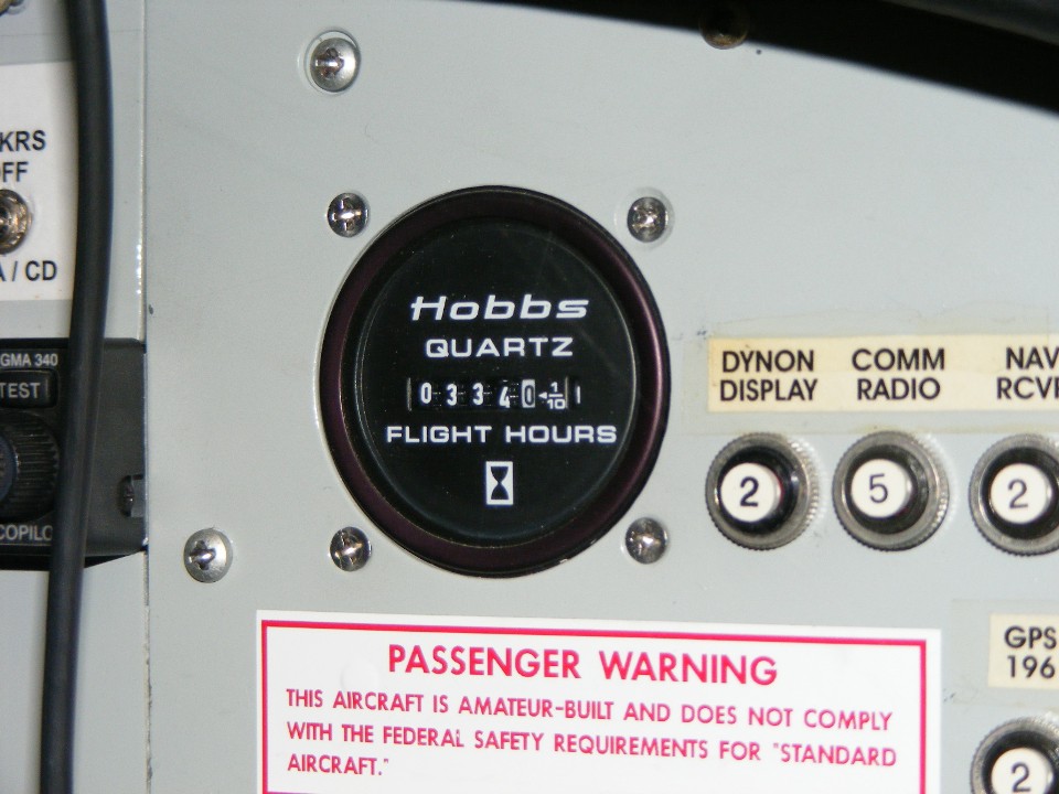
February 20, 2012: It is another federal holiday in the USA with no mail service and the banks are closed. This one is called "President's Day" and our company observes this holiday, therefore I have the day off from my usual duties. It is a sunny day here in the Chattanooga area so I went to the airport to run the engine of my airplane and do the cylinder compression tests I mentioned in the text above. Wendell and I worked together to get his airplane out of the hangar and then bring mine out onto the ramp and turn it into the wind, and to keep the prop wash from blowing into the hangar during my engine test. The battery minder has kept the battery fully charged. I got into the seat, turned on the master switch, hit the boost pump and primer switches for a few seconds, and turned the ignition switch to the start position. The engine started on the first try and I got it into the normal idle range for a few minutes before raising the RPM to 1800 to complete the warm-up. I exercised the propeller governor with no effect until the oil got circulated up to the prop hub. I had previously run the engine on the starter motor with no spark plugs installed right after I did the oil change last month. Turning the engine over that way allowed the oil to get back into all the major areas before today's engine start. Once the oil pressure came up to normal engine operation, the propeller pitch change worked normally. I ran the engine until the cylinder heads exceeded 300 degrees Fahrenheit before shutting down and pulling the airplane back into the hangar. The cylinder pressure checks were normal. I put the cowl back on the airplane and finished up by checking the leaks from my fuel drain valves. They just needed some exercise. I did put down a couple of new clean white paper towels to mark any new fuel drips that may occur. The Hobbs meter has turned over to 334.0 hours.
February 25, 2012: I went into the hangar
today to check the paper towels I put down the other day. Only one of them had any
dripping fuel marks. I exercised the fuel drain valve about five times and moved the
paper towel slightly to one side to see if the dripping will cease.
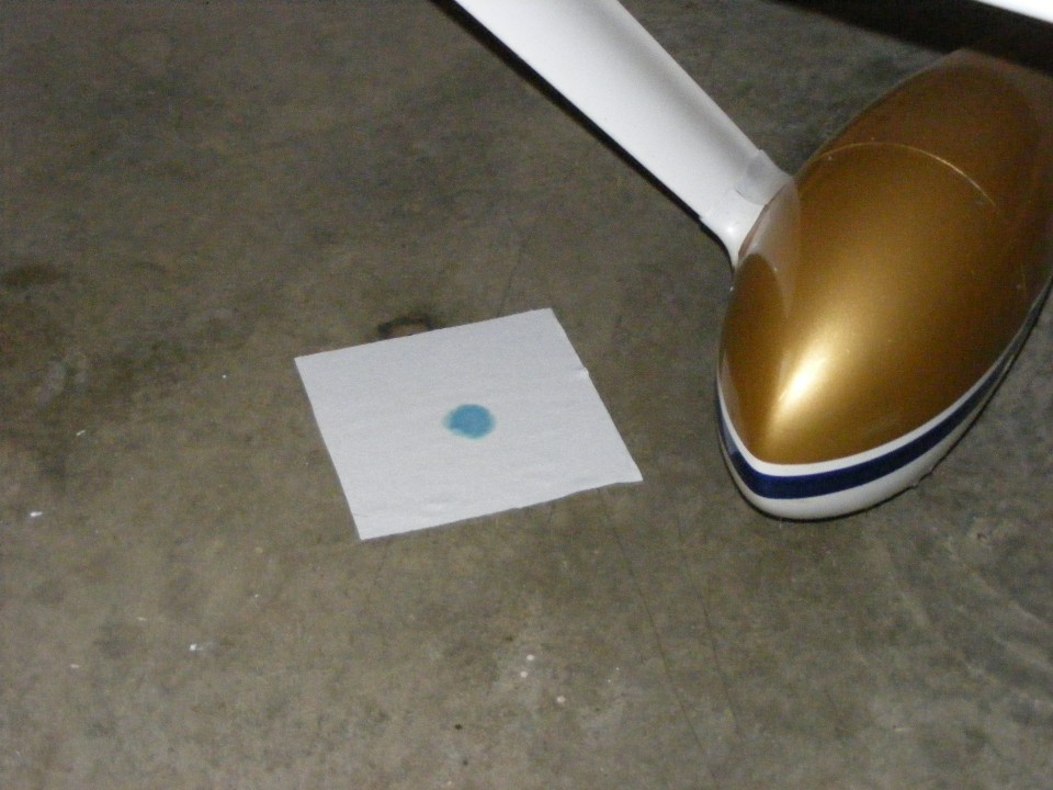
March 4, 2012: I went out to the airport
late this afternoon and found no additional fuel on any of the paper towels. All is
good. I remembered to take a photo of the Hobbs meter today. It shows the
total number of hours after running the engine for compression tests on February 20, 2012.
The high points from this past week were my quarterly appointments with my cardiologist, and my primary care physician/FAA medical examiner. The FAA stress test was last Thursday, March 1, 2012. I passed it with my maximum heart rate of 157 beats per minute on a treadmill inclined 14 degrees while doing a brisk walk of 3.3 MPH. I am scheduled for my FAA medical test on Monday, March 12. I have a trip to Los Angeles for next week to attend a trade show.
March 11, 2012: I used this Sunday to bring my web site pages up to date. The family section has three new pages of photos from my visit to see my son and his family in York, PA on February 4-5, 2012 as I was on my way to New York City for my day job.
The trip to Los Angeles went pretty much as planned except that the return flight from LAX to Atlanta was 1.5 hours late due to a maintenance issue where the angle-of-attack sensor had to be replaced on the Boeing 757 airliner that was my eastbound ride. One of the things I took along on this trip was my pulse oximeter. I asked the co-pilot about the interior cabin pressure during the flight from Atlanta to LAX last Monday. He said it was about 8,000 feet MSL for the cabin pressure altitude. My pulse oximeter showed I could easily maintain my blood oxygen saturation level in the mid-90 percent range. That says I won't have any issues when I get airborne again in my RV-9A.
March 23, 2012: The FAA medical test went as planned on March 12. I got all the paper work up to date for submission to the FAA. My doctor had to prepare his part of the records for this visit. I went back on two consecutive days to do blood pressure checks to show my average pressure. Everything is now reported and we just wait to hear from the medical branch. This could be a three-week wait.
| CLICK HERE for PAGE 357 | Return to MAIN MENU |