Airport Assembly - Page 127.
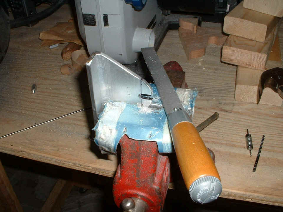
May 14, 2005: The nose of both fuel tanks
have an attachment bracket on them. This is one of the F-996A matching brackets that
will be bolted to the side of the fuselage and bolted loosely to the T-905 fuel tank
attachment bracket. This flat file and a round file were used to get the
slot to the correct dimensions.
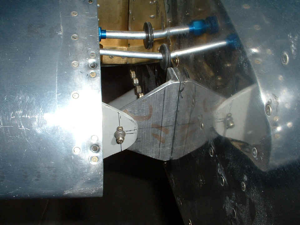
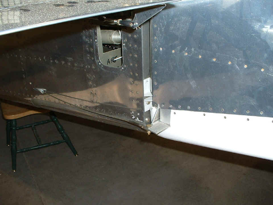
Here is where that bracket lives on the airplane. There are two holes
already in the side of the fuselage under the F-996A bracket ready to back drill the
bracket before I finish it and bolt it to the fuselage. I also put fuel lube on the
threads of each of those blue AN fittings you see reflected in this photo where the fuel
line and vent line connect to the inboard ends of the fuel tanks.
May 15, 2005: Sunday was
cooler than the last few days after a weather front passed by and cleared the skies. I finished drilling the tank attach brackets and got them bolted to the fuselage
and the wing tanks. I also poked the fuel sensor wires through the large grommet on
both sides.
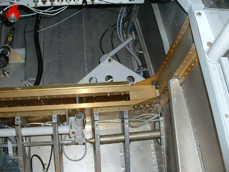
I routed the two air lines going to the LIFT RESERVE INDICATOR (LRI) through
the seat ribs, the wing bulkheads, and along the bottom side wall to the bulkhead that
comes up behind the instrument panel area. I brought along the RG-58 cable from the
VOR/Glide Slope antenna. I have put a few tie-wraps in place, but will finish the
job in the next session.
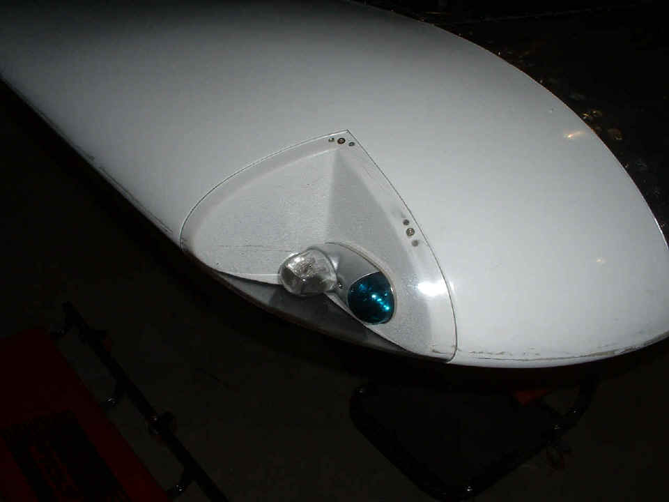
The right wing tip marker light lens got a second pair
of 6-32 platenuts to insure the lens will stay put at 190+ MPH! The second one is on
the underside half way from the corner to the front. I had to remove the wing tip
from the wing and remove the light fixture in order to set the rivets that secure the
platenuts. This also gave me a chance to replace some damaged 4-40 screws.
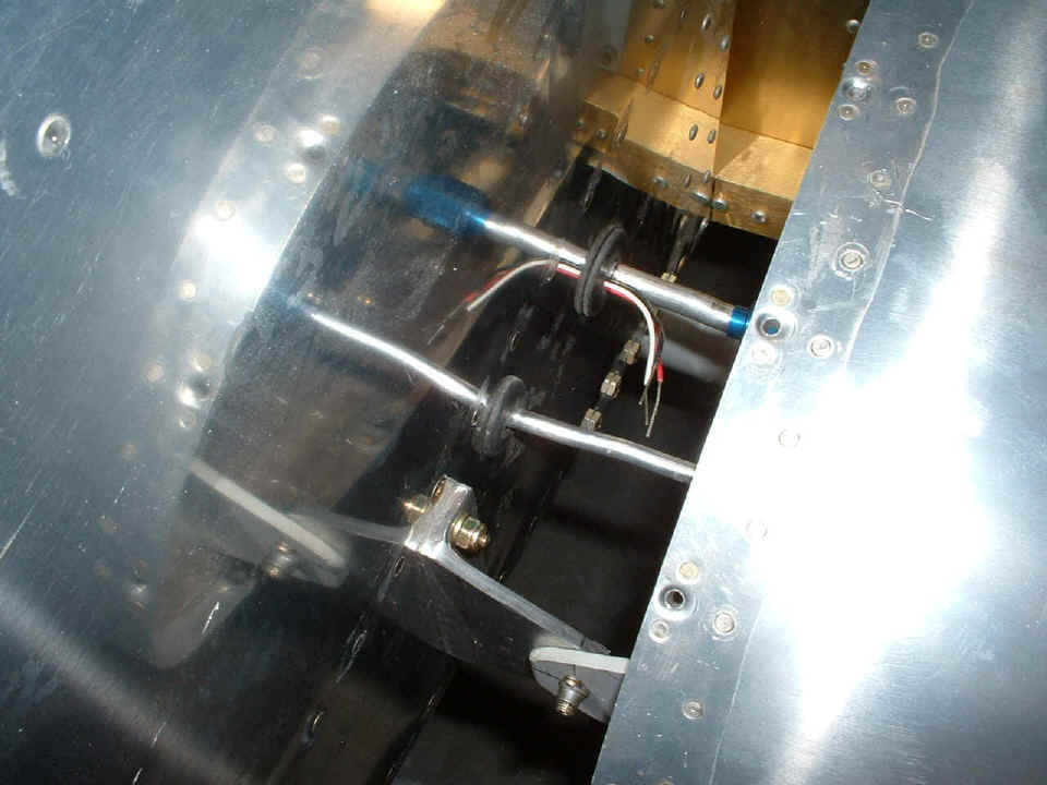
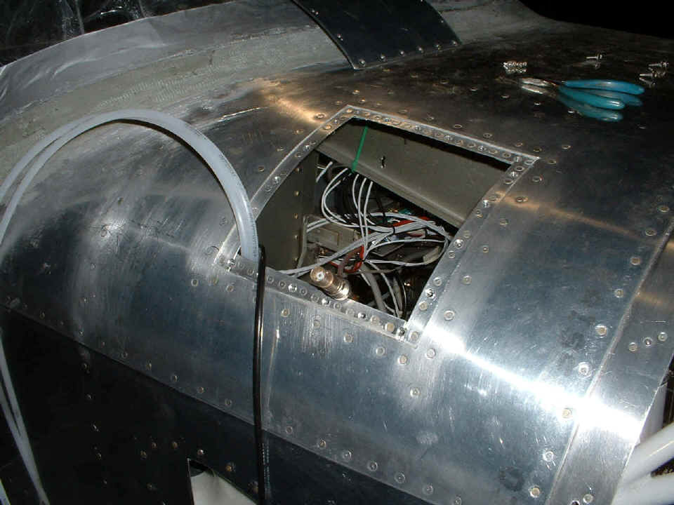
The last picture for today shows two air lines and the RG-58 coax temporarily
strung outside the fuselage via the access hatch. That BNC female splice you see is
connected to the antenna input on the NAV side of the SL-30 NAV/COM receiver. I will
be cutting that coax to the proper length and putting on a male BNC connector very soon.
The air lines will be routed behind the instrument panel to a point where they can
be connected to the Lift Reserve Indicator (LRI) gauge on the main panel. I pushed a small amount
of air pressure through the open lines to mark the ends of one of the tubes with my large
black Sharpie pen. The session was 5.0 hours for today.
May 16, 2005: I ordered a case of AeroShell 100 oil and some oil filters today in preparation for the first engine test which could happen some time next week. Believe me, that day will get full coverage with photos when it is time to check the engine and oil cooler lines for any possible oil leaks while on the ground near the hangar area. But first I have to put in the brake lines again and pump them full of brake fluid.
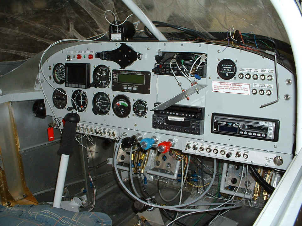
I put in a relatively "short session" today of 2.8 hours. In
that time, I finished routing the RG-58 cable from the VOR/Glide Slope antenna behind the
panel and put on the BNC male connector. It is now connected to the NAV receiver
input and ready for use. I pulled the blank switch panel above the Garmin GMA340
audio panel and replaced the GPS antenna with the new one that has the shorter coax cable.
I actually put my LEFT seat back into the airplane along with my old couch pillows
to work in here this time. No sore knees from kneeling down in there today.
Speaking of Garmin, I called them earlier today to see about sending in my GMA 340
to get the ICS inhibit function repaired. I have an RMA number and will be taking it
out of the basket tomorrow and sending it off to Kansas for service. I will put in
my GPS data power cable and connect that before sending it away. I want to hear the
GPS 296 talk via the headphones first. I routed the two air lines from the LRI up to
a point just under the panel and they are ready to be connected to the gauge on the panel.
I removed the "undersized" rudder stop from the tail and made a new
one that I clecoed in position to check the new limit of the rudder movement. The
only evidence in this photo is the smudged primer paint left on the skin near the rudder
cable and the empty rivet holes there. I also have to make a pair of "rudder
cable exit covers" to prevent any moisture from coming in those locations into the
tail.
Rich Nadig stopped by to check on me early in the afternoon and I put him to work with a wrench in his hand holding one of my brake line fittings where it exits the fuselage in front of the RIGHT main gear leg. It needed the nut inside tightened up a bit since it had loosened when I removed the brake line inside during the wing bolt work. It really got crowded in that corner of the fuselage with the two new air lines and two coaxial cables running past the fuel line, fuel tank vent line, and the brake line crowding into that corner just ahead of the wing bulkheads.
| CLICK HERE for Airport Assembly - Page 128. | RETURN to MAIN MENU. |