Airport Assembly - Page 128.
May 17, 2005: I received oil filters from
Spruce today, and they are the wrong ones. My right-angle oil adapter uses a
different thread size on the base of the filter than the ones that were called out for the
Lycoming O-320 on the Aircraft Spruce & Specialty web page. I will have to call
about sending those back tomorrow and ordering the correct ones. I stopped by a
local machine shop to get my 5/8" torque wrench extension welded together and tried
it out on the prop when I got to the airport after lunch.
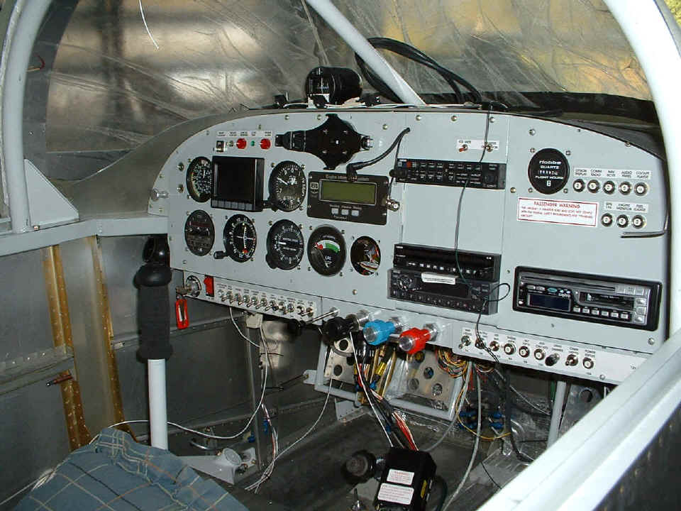
The focus today was on rewiring the panel. The GPS 296 data/power cable
is now connected, but there are some issues to be resolved. The data stream is not
getting to the Smart Coupler in the NavAid auto pilot. The audio output from the 296
is just a "buzz" when routed through the GMA 340 audio panel. I have heard
the audio on a test speaker, so I hope that all is needed is a good resistive load around
10 ohms across the output from the GPS, then a 1K resistor in series with the input to the
GMA340. I will speak with Garmin about it in the morning. There is a little
white wire hanging down in the upper left corner of this photo. That wire runs up
the center support bar from the dimmer circuit that feeds the light in the compass on top
of the panel. That wire will be connected to three white LED's up on the bottom of
the roll bar that will be used to illuminate the main instrument panel for night flight.
I still need to run the wires for the map lights that will be on either side of the
fuselage on the wing bulkhead covers. One of the lights will be near the top of
those two gold-anodized angles you see near the left side of this photo.
Now let's talk about what did work. I talked to Unicom on the SL-30
com
radio and got a good report on audio quality. I tried it through the GMA 340, and
via the direct connections at the bottom of the panel with good results both ways. I
found the flexible pitot line had been crimped when I first sat down in the seat and
looked at the airspeed indicator showing 75 MPH. I tugged on the line inside the
fuselage and it opened up the blockage. I could see where it was crimped in between
the root rib and the side of the fuselage - an easy fix! I removed the electronic
fuel gauge from the panel and let it hang down by the cables. This will provide easy
access to the control button on the back of the gauge to run the calibration procedure as
I fill the fuel tanks for the first time.
I also connected the air lines to the back of the lift reserve indicator gauge.
They are not yet connected at the other end inside the wing. The minor
disappointment today was discovering the worst possible placement of the BNC connectors
for the capacitive fuel sensors. They are BOTH lined up with plate nuts that hold
the wing root fairing in place. I will have to cut two screws very short to use in
those locations.
When I got home tonight, I called the AB-DAR in the Birmingham, Alabama area
and asked if he would inspect my airplane. I let him know that I had already talked
with Nashville FSDO and the fact that all the inspectors live about 100 miles or more from
Chattanooga. I mentioned that he had been referred to me by David Edgemon and
discussed the RV-9A and other pertinent details. We set a tentative date for the
inspection of June 8th. That should work out about right with everything else that
is going on with my flight training and the completion of the airplane.
May 18, 2005: No
pictures today, just the facts. I ordered the correct oil filters from Spruce and
got an RMA number for the wrong filters. Although they came from their warehouse
south of Atlanta, all returns have to go to the California location.
I continued my work on the interface from the 296 to the Smart Coupler
interface of the NavAid Devices auto pilot -- still no luck. I tried the second
serial port from the 296, and that did not work either. That took me through ONE
hour of work at the airport and I called it a day to take the NavAid controller to their
shop here in Chattanooga. I pulled the entire instrument panel and took it all into
their shop. But first I stopped at the UPS facility and shipped my Garmin GMA 340
audio unit to them, and the box of incorrect oil filters to the Spruce facility in Corona,
California.
The wing leveler controller was removed from my panel on the bench at NavAid
when I got there. The Smart Coupler software has been upgraded since I bought my
unit. The chip was changed and the tech tested the interface on a laptop computer.
The unit can now work on 9600 baud from the GPS, but since the rate from the GPS
296 is 4800 in NMEA mode, I had him set his serial port to 4800 baud and it worked just
fine.
When I got home, I found the envelope from Van's in the mail box with the
correct four bolts to finish the wing bolt installation. I finished up a side
project at home tonight to wire up my second GPS data/power cable for automotive usage.
I then connected the GPS 296 to my computer and checked it out in Garmin host mode,
and NMEA mode. Both worked fine with my Street Atlas USA program. All I have
to do now is make it work with the autopilot tomorrow at the airport on the data/power
cable in the airplane!
May 19, 2005: I went to the airport after
lunch to get the wing bolts in first thing. Then I started work to get the serial
port working from the GPS to the wing leveler controller. Success was there for me
this day. USE THE FORCE, LUKE! This was also the first
day for Star Wars Episode III.
I decided to leave the panel out of the frame until the GMA 340 gets back from
Garmin repair. That will give me a chance to finish the audio impedance matching
circuit for the GPS 296 voice alert. Then I got started putting the wiring in
position at the map light locations on each side of the cabin, and to connect the wire for
the LED panel lights that will be mounted on the roll bar on the pilot's side.
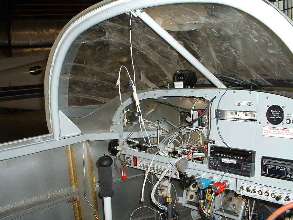
You can see the wire for the LEFT map light hanging down between the wing bulkhead
angles against the left wall of the cabin. I connected the dimmer circuit wire
coming up the inside of the center windshield bar to the positive wire to the LED's and
put a piece of heat shrink over the soldered connection. You can see the string of
three LED's hanging by the wire. As I was sitting there, I designed an aluminum
mounting plate for the LED's. And here are all three with one LED light sitting in
the approximate position it will have when fully assembled. I will paint them with
the pewter gray paint tomorrow morning at home.
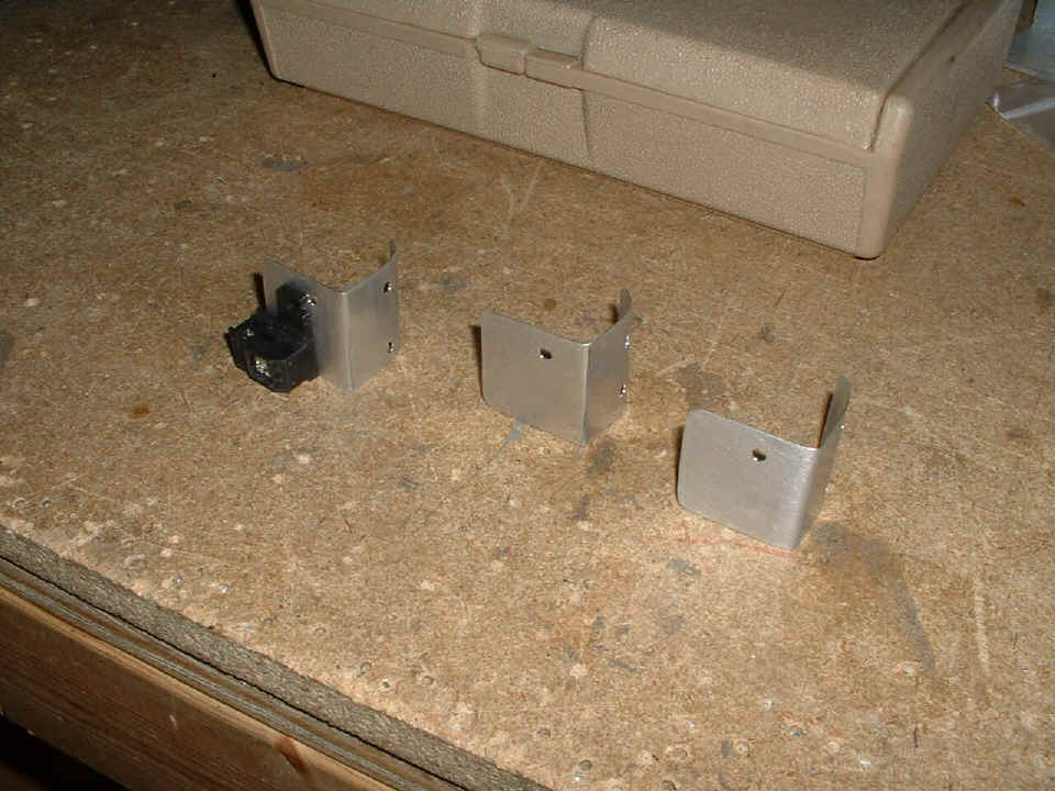
There is one mounting hole which will get a 6-32 screw and nut to hold the LED to
the aluminum plate. There may also be an adhesive pad behind it to help secure the
LED. The right-angle bend will put the curved surface of the bracket up against the
back side of the roll bar and two additional 6-32 screws will secure the bracket to the
roll bar. There is enough aluminum there to allow me to bend the angle of the plate
to focus the LED light patterns on the center of the instrument panel. Today had a
2.9-hour session that was win/win all the way!
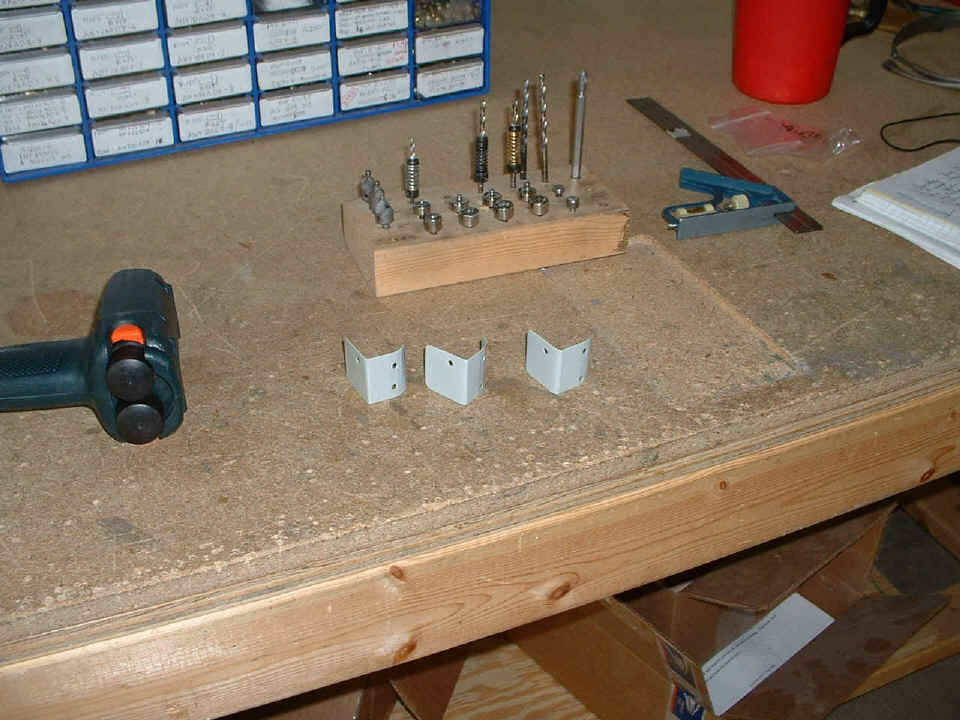
May 20, 2005: No trip to
the airport today, but I did get the parts you see above painted in the garage using the
top of the saw as a small work table. Total time required was only 0.2 hours.
Friday's are grocery days, and other chores, but usually not for airplane construction.
May 21, 2005: It's a Saturday again and I
managed to get in a good six hours today at the airport. The LEFT rudder stop went
back on the tail of the fuselage very quickly using CS4-4 blind rivets. Here is a
picture of the painted parts that will mount the white LED's above the instrument panel.
The only thing I forgot was the hardware to mount them. I guess I will save
that for tomorrow afternoon after ACE Hardware opens. I climbed inside the cabin
again to install a resistive network to the audio alert input of the audio panel. I
hope it will make the audio alerts from the GPS 296 work correctly with the Garmin GMA 340
audio panel. I won't get a chance to check it out until the unit returns from repair
at Garmin. It arrived there yesterday according to the UPS tracking report.
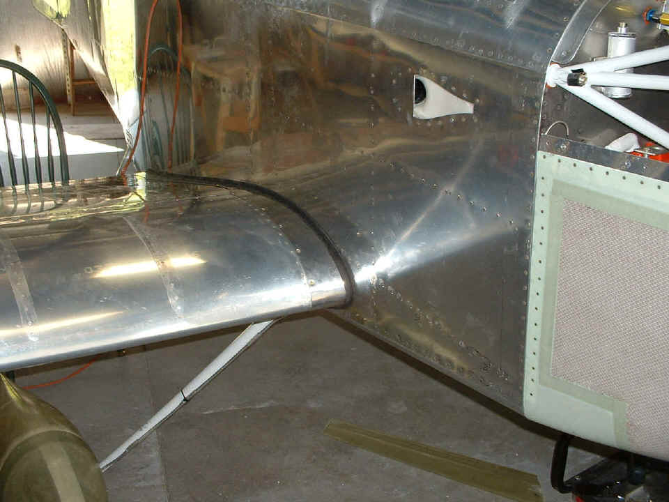
Next on the agenda was to get the wing ready for the aluminum wing fairings at
the root of the wing and the fuselage. Why? Because the intersection fairings
for the gear leg fairings must have the wing root fairing in place before the intersection
fairings can be installed. The intersection fairings set the angle for the gear leg
fairings. The gear leg fairings have to be set before the wheel pants can have their
intersection fairings trimmed and then secured to the wheel pants. Now that all that
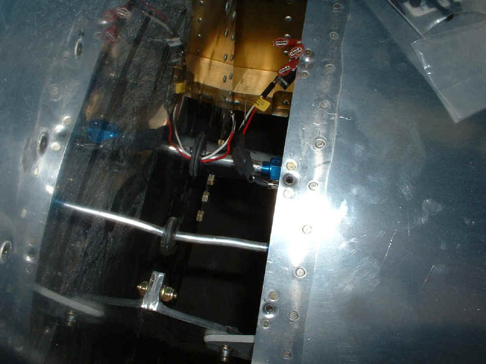
has been said, you know those fuel sensor wires in the second picture from the top of this
page? They now have their very own rubber grommets in the side of the fuselage and
have spade lugs crimped on the ends. Then they were connected to the wires from the
fuel sensor capacitance-to-voltage converter circuits. I turned on the avionics
master and the fuel gauge works, but will need to be properly calibrated for both fuel
tanks. Before today, the fuel gauge always had the word "OPEN" displayed
on the small LCD screen that now has numbers displayed on it.
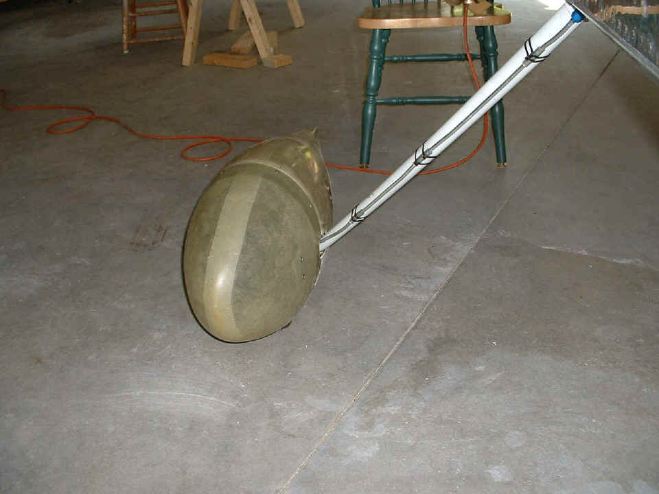
Down under the wing, the wheel pants are secured again as they were at home in
the garage. I found that the extra tire pressure has expanded the tires and that
required some additional Dremel sanding to open the bottom openings around the tires.
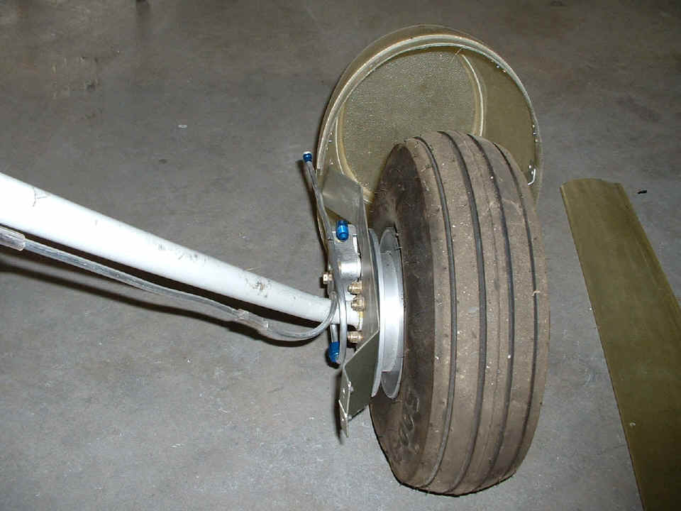
The brake line on the RIGHT gear leg seen below was fine and only needed to be
reconnected and secured with nylon tie-wraps this time. I tried on the fiberglass
gear leg fairing and made some minor trim adjustments to the shape at both ends.
Over on the LEFT gear leg, the brake line expansion joint was reshaped and
about five inches of brake line was cut off and a new flare was put on the new end right
after I took this picture. After the end was prepared, the brake line was put back
in its proper position and secured by tie-wraps also.
Here is how I left both wings at the end of the day. The aluminum
intersection fairings and rubber edge moldings are in position on both wings at the side
of the fuselage. I cut short a total of FOUR #8 flat head screws to use in these
fairings at the locations of the fuel sensor BNC connectors and at the last screw location
above the flaps at the wing aft spar location.
That completes our eight pictures for this page. In the next session, I
should be moving ahead with the intersection fairings and putting the hinges in the
trailing edges of the main gear leg fairings. When that is done, it will be time to
pull off the wheel pants and pump up the brake lines with fluid. Oh, I almost forgot
about putting the nose gear leg fairing back on the airplane. You can see a picture
of that in a wide shot next time when I show you the main gear leg fairings and
intersection fairings all in place.