FINISHING - Page 112.
April 10, 2005: It is a wonderful day
outside, but I kept the garage door closed since it was cooler inside for three hours
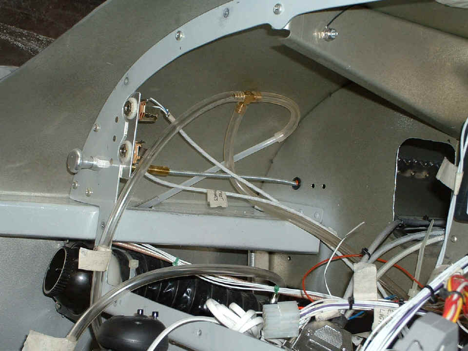
worked today. I realized I had a better flexible air line to connect to the static
line that came with the kit from Van's. I moved the brass "T" connector
that feeds the altitude encoder near the static line as it comes behind the panel. I
then put TYGON plastic tubing from the "T" to connect to the static circuit
behind the airspeed indicator on the panel. I also realized I needed a handy ground
point for the light in the "whiskey" compass mounted on the dash panel. I
used a 3/4" 6-32 screw, lock washer and a standard nut to secure the screw to the rib
you see at the top of the photo. Then I put two stainless steel flat washers and the
Nylok nut on the screw to capture the ground wire from the compass light between the
washers. I connected the other light wire to the dimmer circuit. The compass
is mounted above the panel just at the right edge of this photo.
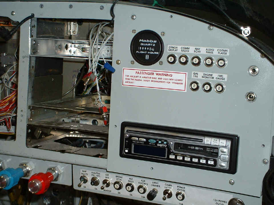
The right side panel with the stereo, Hobbs meter, and circuit breakers went
into the main panel next.
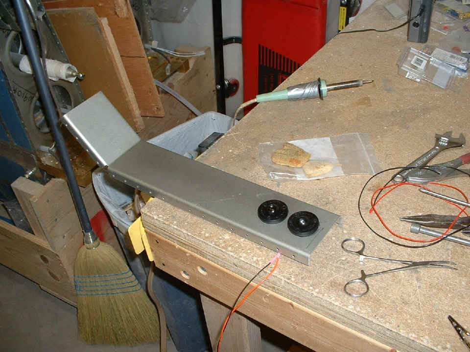
I got out my "eyeball" map lights and attached them to the side panel
cover that fits over the wing bulkheads. I used the soldering iron to connect the
lights in parallel to the Tefzel wires that will go behind the panel for power
connections. I turned off all the shop lights in the garage except the one light
switch cord I could reach from the left seat in the airplane. I connected the
battery ground cable and measured 10 milliamperes drain, which is the LED on the power
button of the stereo. I turned on the main bus and experimented with the eyeball
lights in their final position on my side of the cabin. I tried them on straight 12
volts, and on the dimmer circuit. I decided to put them on the 12-volt bus via a
switch/breaker I already had on the right switch panel. I was really surprised at
how dark it is my garage with all the shop lights off, even at mid-afternoon. There
is very little light leakage around the edges of the garage door, especially when I put in
my wedge blocks to keep the cool (or warm) air inside.
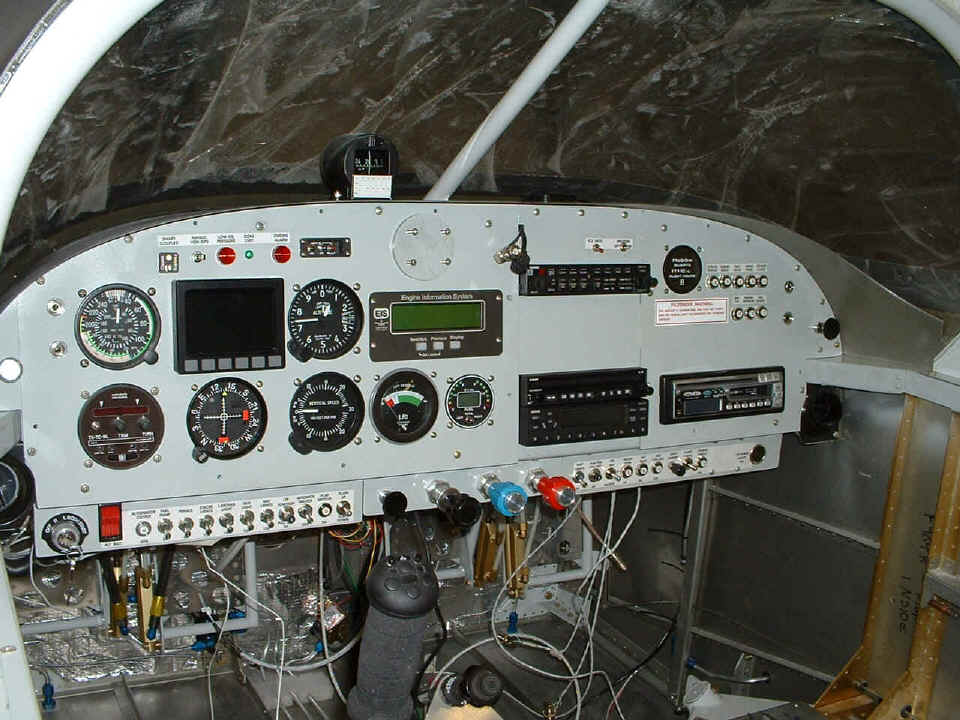
And this was a psychological boost that I needed, putting the main instrument
panel back in the main panel and filling up the radio stack. I changed the strip of
labels across the top of the Dynon unit and the warning lights there. The green
light now says COM XMIT above it. When the mic is keyed, it lights up. It
should minimize my "stuck mic" issues. I also put the label on the switch
panel that lives above the Garmin audio panel. The switch on the right turns on the
stereo speakers on those occasions when I want to use them on the ground, engine off, like
air shows, etc. The other switch controls the intercom inhibit function of the
Garmin audio panel. It can be set to NOT mute the music channel when my passenger
and I are listening and we want to talk to each other over the music. Activity on
the COM radio always mutes the music, but if the pilot isolation is selected on the Garmin
audio panel, the pilot can listen to the com radio and the passenger can listen to the
music. There is also a blank panel the same size of a Garmin GNS 430 GPS/COM/NAV
unit, which hopefully will occupy that space some day.
As for the wires hanging down behind the panels, there are aux mic and phone jacks
that connect directly to the COM radio and can be used even if the Garmin audio panel is
removed from the airplane. I will make a bracket for them and mount them down below
the throttle quadrant panel. There is also a pair of circuits connecting to the
audio panel. One for audio output to a recording device, and another which is used
for an altitude alert warning. The Garmin GPS 296 has voice output capability to
drive that audio input. Although I have a GPS 196 now, I have been considering the
296 for the panel and passing the 196 to my son who is a student pilot in Texas.
There are also a couple of RS-232 outputs hanging down from the Dynon D-10A and the Garmin
GPS data power cable. Over on the right side is an RG-400 cable hanging down waiting
to be connected to the VOR/ILS antenna when I get to the airport.
After a dinner break and watching the end of the Masters Golf Tournament, I went out to the airplane for a quick night lighting test now that the instrument panel is installed. I can see now why I thought of those eyeball lights as map lights only, not panel lights. The only instrument that is properly lighted by the eyeballs is the airspeed indicator. I had been thinking about using the white LED's under the rim of the forward top skin and operating them on the dimmer circuit. I have seen that is exactly what is going to happen. I will let you know in the next session. I put the battery charger on for the evening and we resume speed tomorrow. The construction time on the airplane is at 1798.1 hours. You know what happens in the next session!
April 11, 2005: I called Abby at Flightline Interiors to order my seats, the interior including insulation, and the carpet package today. I provided her a link to a custom web page with the locations of my stereo speakers and the notch for the Tugwell canopy bracket on the aft wall. After lunch, I took a ride to the Collegedale Airport to visit the airport manager, Frank Zarski, and to see the hangar space where I will be assembling the airplane. After that, I visited the paint shop a few miles across the state line in Georgia to get some advice from the guy who will be painting the airplane when the time comes. I also stopped by a local body shop that does wrecker service and towing to ask about getting the airplane to the airport. He referred me to another towing company. It is after 5:30 PM as I write this, and except for going out to take some measurements for Abby, I have not done anything to the airplane today.
After dinner this evening, the television schedule was bad, so I sat down in the airplane and tried out some extra panel lighting using three white LED's in series for 12-volt service, and put them on the dimmer circuit. I also put the eyeball lights back on the dimmer circuit and tried them all together with better results than I got earlier with just the eyeballs only. I see that I need to put one eyeball light on the other side of the airplane to illuminate my switch panel on the right side.
April 12, 2005: I have
been working on estate business and I had a phone call and a fax from the company for
which I am doing contract web page work. I also got an email from Abby at Flightline Interiors with her first sketch of the interior she is
proposing. The pewter gray color is the dominant color and a royal blue is the
accent color. I just talked with her while I am doing this page, and I promised her
I would provide a "starship" pattern for the side wall panels instead of the
"S" pattern you see below. You can see some of her
photos on my web site HERE.
Here is my first attempt at a starship for the stitching pattern on the side
wall panels.

April 13, 2005: I had more
web page work to do during the morning and again after lunch. I went out just before
lunch to see the other tow truck company in town. He had a bigger truck than the
first guy. He seems interested in helping me get the airplane out to the Collegedale
airport. He wants to stop by to look at the airplane before we set the date to make
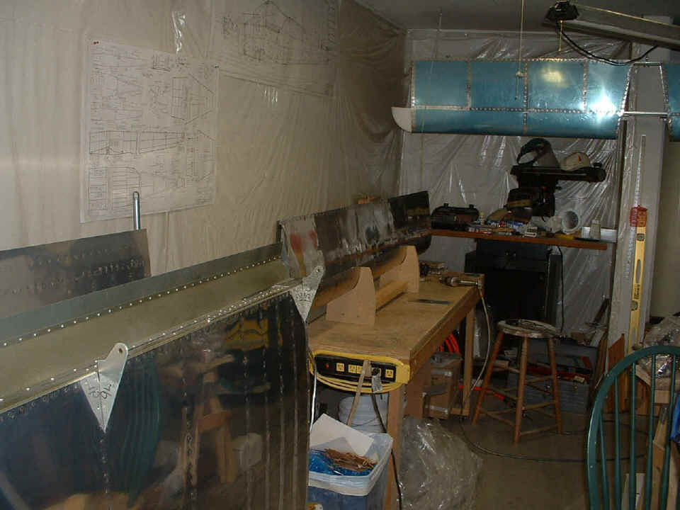
the move. I put in about two hours late in the afternoon working to move the wings
outside and clean out the extra stuff stored between the wings that I won't be taking to
the airport. I also stripped off more of the blue plastic from the wings and the
flaps. I removed the flaps since I don't want them flopping in the breeze on the way
to the airport. It was during the removal of the flaps that i noticed some of the
trailing edge rivets on the flaps were not set very well. I decided that using the
-3 rivets per the plans was the problem. The few that popped loose when I was
pulling off the blue plastic have been replaced with longer -4 rivets. I have
decided I will replace all of them on both flaps before I head to the airport.
I got out my aileron/flap jig and started drilling out some rivets in a late
evening half-hour session. I stopped at 11 PM and will get back to it tomorrow.
I used my squeezer to partially set the rivets, then lay the flap down on the table
using the back-riveting steel plate to finish setting the rivets double-flush on the
trailing edge of the flap. Part of that two-hour afternoon session was clearing off
the table and bagging all the electric connectors and plastic bushings that had been on
the work table. I started to think about the things I have to put on the tow truck,
and preparing everything for that day (soon). I will also take the ailerons off the
wings now that they have served their purpose during wing tip alignment and installation.
I also want to get the wings up on the work table one more time to put on the
platenuts at the wing root to secure the wing-to-fuselage fairing strips. I have
also been thinking about doing the dusty fiberglass work here in the garage on the
Aeropoxy fillers around the windshield. There are four other airplanes in that large
hangar. I don't want to be a bad neighbor with dust getting on their
airplanes. Mine will be the smallest and least expensive one in that hangar.
April 14, 2005: A good
day today with a visit from J.R. Broome from the towing company. He wanted to see
the airplane and consider how it will be placed on his tow truck along with the wing cart
and my work table for the ride to the airport. I also finished the replacement of
all the trailing edge rivets in one of my flaps. Van's drawings specified AN426AD3-3
rivets in the double-countersinked holes of the AEX trailing edge and the two flap
skins. I ended up putting AN426AD3-4 rivets in there and got a good double-flush
shop head during the back-riveting process.
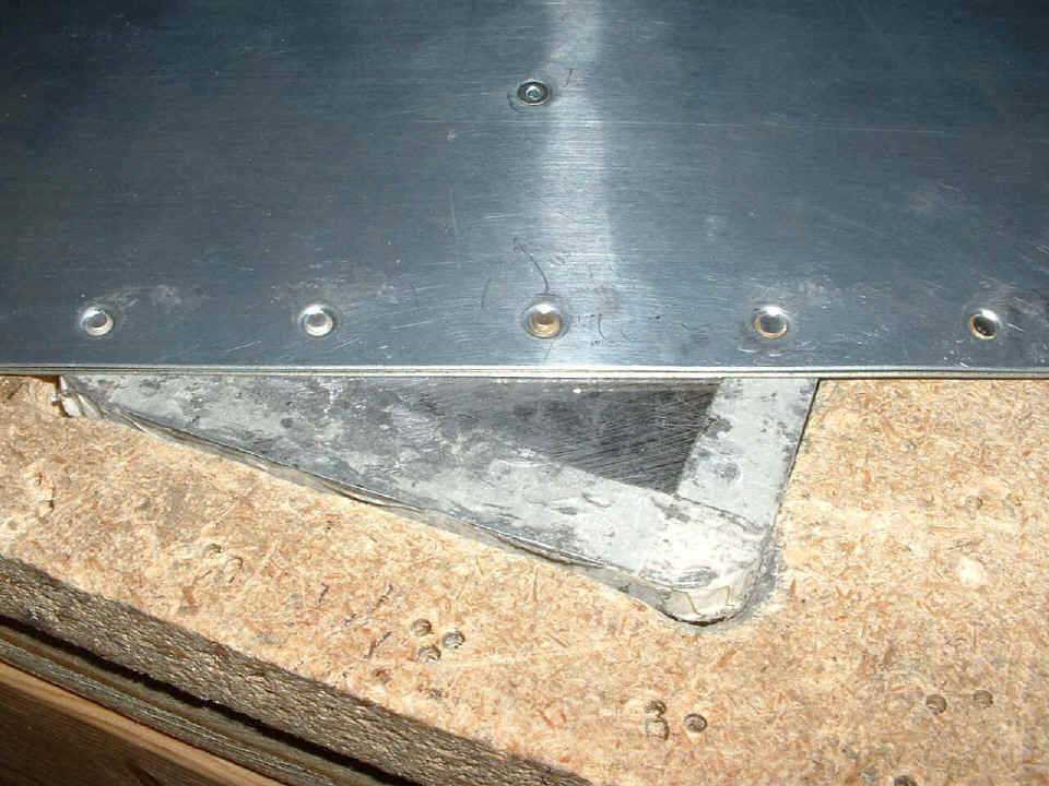
This close-up photo of the trailing edge on the back riveting plate in the work
table shows the difference in the rivets. The two rivets at the left side of the
photo are the -3 rivets which were first installed per the plans. The rivet in the
center is the replacement -4 rivet after using my squeezer to partially set the rivet
through the AEX wedge (trailing edge) and the top and bottom flap skins. The two
rivets on the right have had the full treatment on the back riveting steel plate.
Notice how the shop head had been formed to fill in the countersunk hole on this, the
bottom side of the flap trailing edge. The flush factory heads of the rivets are
down against the back riveting plate in the other side of the double countersinked holes.
I also checked the other flap and realized that I had already used longer rivets in
that one. I put the flap on the work table and used the rivet gun on the back riveting
plate to get a fully formed shop head. I could see the difference when
I was finished.
I pulled the wing cart out on the driveway again. The ailerons were
removed and put away. I stored the flaps in the bottom of the cart for transport to
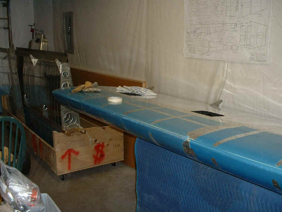
the airport. I also tested the fit of the horizontal stabilizer between the wings
with it wrapped in the blue padding blanket you see in the photo below. The right
wing is up on the work table again. I have to put on the platenuts at the inboard
rib for attaching the wing fairing to the fuselage. That is where I will resume work
in the next session. And for those who don't know yet, the bare wing weighs about 60
pounds. I lifted it out of the wing cradle/cart with my leather gloves using the
inspection holes as handles. I put it on my four-wheel dolly to roll it into the
shop, then lifted it up on the work table. After that, the other wing and the cart
were rolled back inside the garage door.
A neighbor from up the street stopped by just as I was finishing up before dinner time. His stop was the second time today I gave the "tour" of the airplane project to visitors.
| CLICK HERE for Finishing Page 113. | RETURN to MAIN MENU. |