FINISHING - Page 109.
March 29, 2005: Another warm day after the
cold and rainy Monday that was yesterday. The focus for most of today was on
fiberglass parts. My Dremel sanding drum got a real work out by the garage door with
the fan blowing the dust out the door as soon as it was created. Here is the bottom
cap to the rudder clecoed in position. Because the platenuts near the tail light are
so close to each other, I made sure I kept the holes offset from each other.
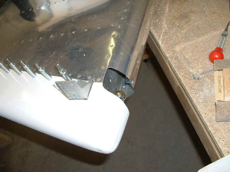
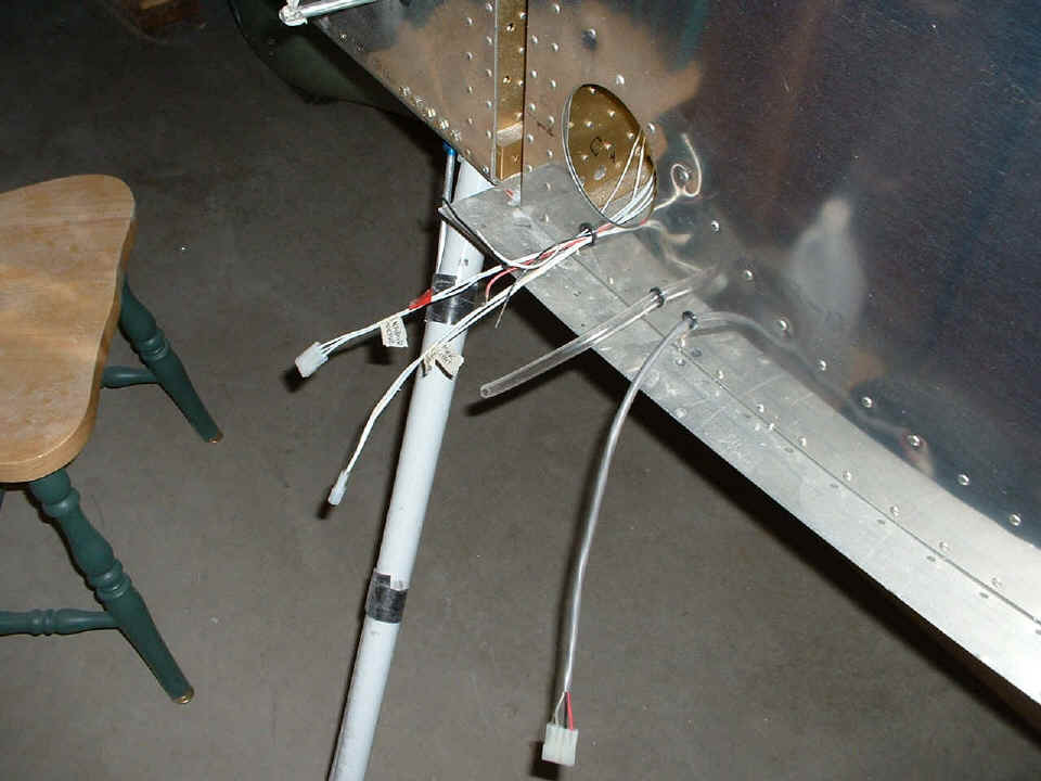
I looked at the lower rod end bearing that secures the rudder to the bottom of
the rear spar of the vertical stabilizer and the fuselage aft bulkhead. This is also
the way the wires going to the tail light and strobe unit must be routed.
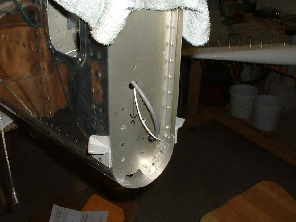
Seeing that location on the rudder prompted me to relocate the exit point for
my wires. Don't get confused by what you see below. I am using the abandoned
hole on the centerline as the temporary storage location for the excess wire.
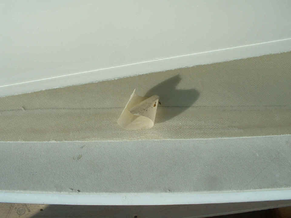
The photo below may not look like the RIGHT wing tip, but that's OK. I
was trimming it the same way I trimmed the LEFT one the other day when I noticed this gap
in the fiberglass where there was nothing there but gel coat. It
is a factory defect. I grabbed this
discarded piece of masking tape to mark the spot while I took this photo. Looks like
I am going to be mixing up some epoxy and doing some patching. Two or three layers
of glass should be enough to fix this problem. I have some other items that need
some attention, so there will be a fiberglass day very soon.
At the bottom of page 108, I posted a quick note about the web site being back
to normal. After my four-hour session this afternoon, I stopped for a dinner break,
the local newscasts, and a check of my email. Another RV-9A builder (Tom Fries)
asked me how I routed my pitot line from the wing root to the instrument panel. I
realized that I did not provide any photos other than the one below originally posted on
page 107 showing the tube at the wing root.
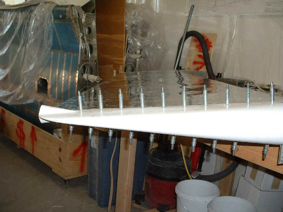
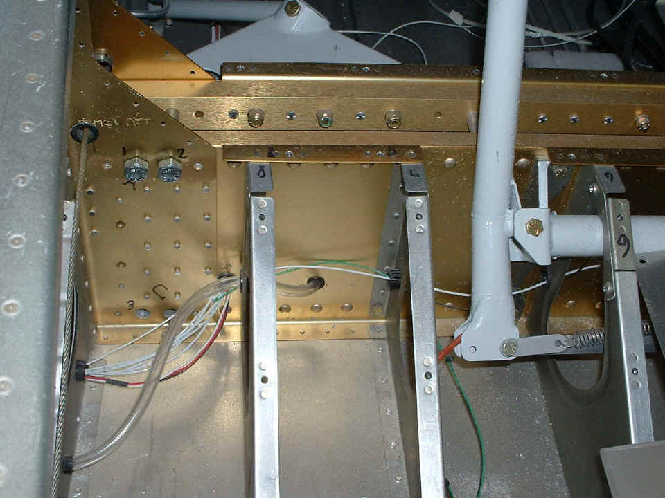
This photo is looking inside under the left seat area. The Tygon clear
plastic tube is routed low to pass under the aileron push rod tube to be installed from
the joystick to the aileron bellcrank in the wing. The tubing passes through the
seat rib then turns through the wing spar bulkheads inboard from the bolt area that will
secure the wing spars. While we're here, let's talk about those regular bolts you
see in the two upper large wing spar bolt locations. They measure just 0.003"
smaller in diameter than the close tolerance wing bolts from Van's that will ultimately be
installed there and down at the bottom of the wing spars when they are inserted in the
fuselage. Since the steel weldments for the main gear legs were first installed,
they have moved slightly from the weight of the engine (and me) and will have to be
relocated when it is time to put the wings in place. I first talked about these
bolts on page 96 on February 23rd. I will document the procedure in photos when I
get to the airport and insert the wings in the fuselage.
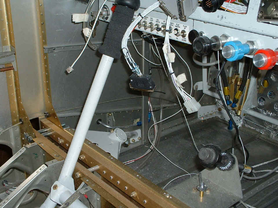
The pitot tubing continues forward from the wing area along the floor. I
will be tucking the tubing and the wires under the lower longeron when the carpet goes in.
You can see the fuel vent line running up the F902 bulkhead. The wires and
the pitot line will go along beside the vent line with tie-wraps up behind the panel, then
through the area just above the fresh air scat tube to the eyeball vent. You can see
the clear tubing for the pitot system hanging down near the mag/starter switch in this
photo. There is enough extra tubing to install on the TEE fitting on the back of the
airspeed indicator before the main removable instrument panel is positioned and secured to
the fixed panel. I put some masking tape on the clear tubing to mark it as
the pitot tube.
The total time on the project now stands at 1777.8 hours of actual construction on the airplane since October 2002.
| CLICK HERE for Finishing Page 110. | RETURN to MAIN MENU. |