FINISHING - Page 105.
March 16, 2005: I put in an evening session
of 2.9 hours after dinner tonight. That brings today's total to 5.2 hours working on
the project. The upper gear leg intersection fairing was the next thing to go on the
nose gear leg. It needed a small amount of trimming on the front side to properly
fit the gear leg fairing. I lined it up with the aircraft centerline and drilled
four holes where I will install platenuts and screws when I get the cowl off again.
Before I put this intersection fairing in position, I made sure the horizontal stainless
steel rods were installed to firmly position the bottom aft edges of the cowl to the
firewall hinges.
Then it was time to turn my attention to the wheel pants:
nose wheel edition. I enlarged the wheel opening with my Dremel sanding drum and made lots of
fiberglass dust as usual. I then did some preliminary fitting of the U-813A
fiberglass wheel fairing over the tire and the attach brackets you see on the side of the
nose wheel yoke assembly. I used two pieces of insulation scraps stacked and taped
to the tire to get approximately 1/2" clearance above the tire inside the wheel
fairing.

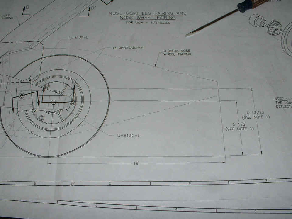
The drawing tells how high the center line of the shroud should be from the
bottom of the tire. Note 1 says these dimensions are when there is NO LOAD on the
tire, as in off the ground. I checked the current height of the axle to see how much
below 5 1/2" it is now due to the weight of the engine, etc. Then I subtracted
the difference from the 6 and 13/16" measurement to check the alignment of the U-813A
wheel fairing at the aft end.
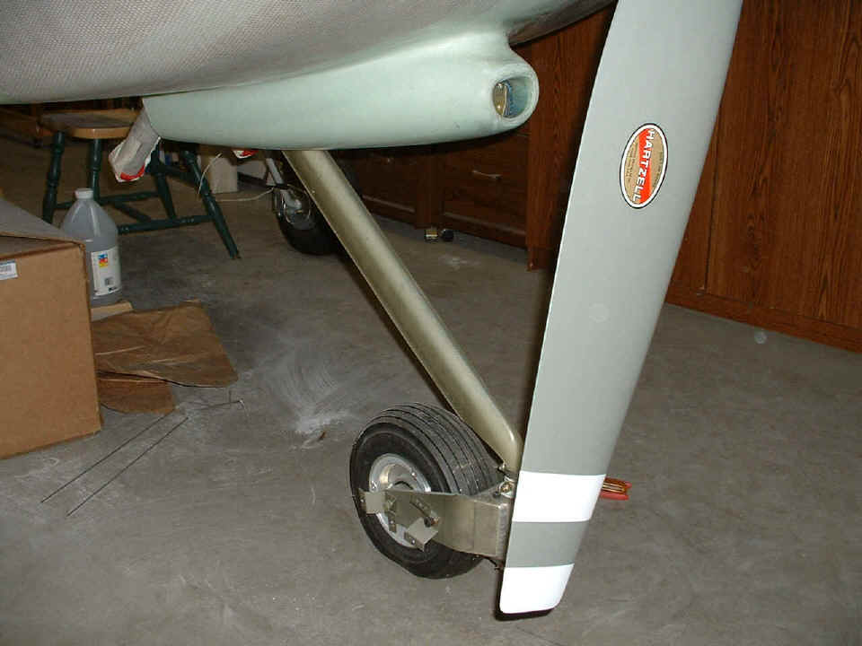
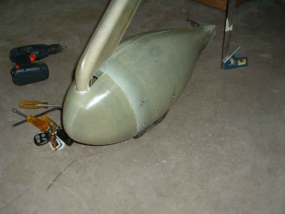
I set up my combination square with the correct height and put some masking
tape around the steel rule at that height. At that point I drilled the first hole
and put in the top screw you see in this photo. It is in the top hole of the forward
bracket on the yoke. I had been using the roll of masking tape to prop up the aft
end of the wheel fairing. When I was satisfied the angle was correct, I drilled the
second hole and installed the lower screw. Look carefully and you will see the
platenut rivets on the lower bracket reflecting through the fiber glass. When I went
to the other side to repeat the process, I discovered the two front attach brackets were
not aligned with each other. I had to remove the screws and slide the shroud back
enough to see the front edges of the front brackets on both sides. The appropriate
Allen wrench was found to fit the cap screws underneath and the change was made to the
bracket on the other side before drilling any holes over there.
The front two screws were installed on the other side, then I adjusted the other two brackets that are centered on the axle to allow me to see the platenut holes faintly through the fiberglass. I used a #40 drill bit for the "pilot hole" to be sure I would not damage the platenut threads. That allowed me to see through the small hole in the fiberglass and decide if I needed to "walk the hole" into alignment when I put in the larger drill bit to fit the #8 stainless screws that secure this thing. Next session we get to install the fiberglass nose piece, and drill the tow bar access holes. I also have to acquire the correct size hose clamp to fit the bottom of the gear leg fairing. The one I had on hand proved to be a bit too small.
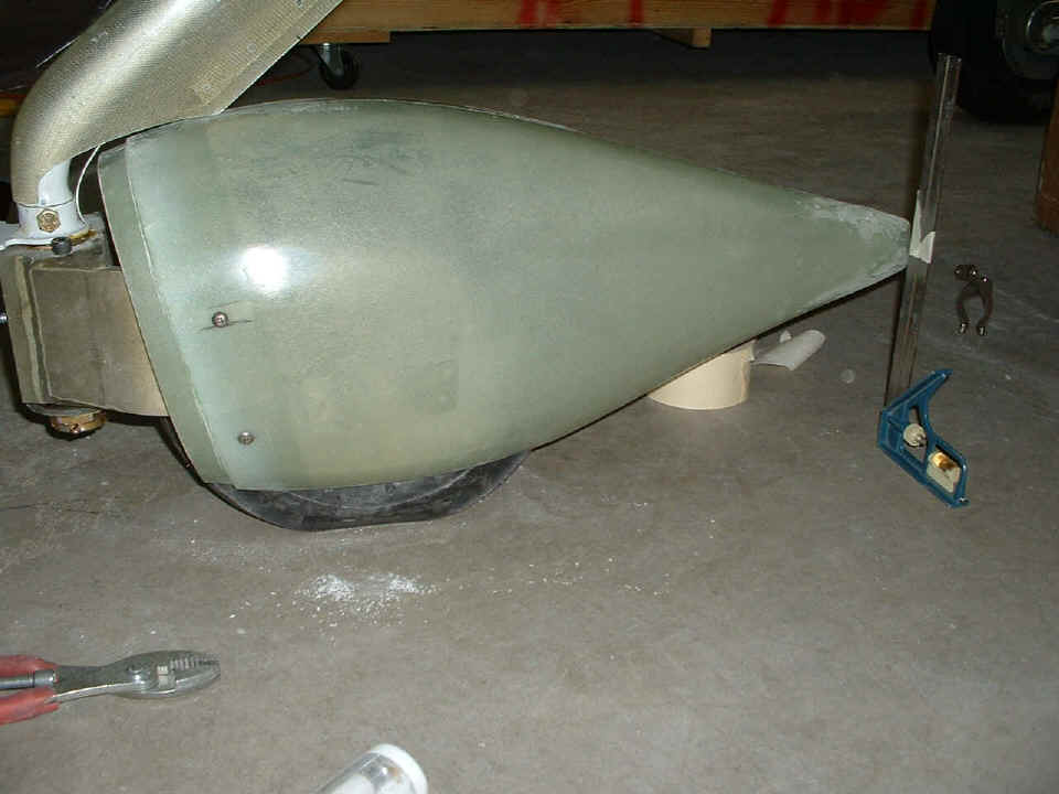
March 17, 2005: St. Patrick's Day. At least I am working with GREEN fiberglass. When I put the nose piece on the wheel fairing, I discovered I missed one dimension when I installed it. It was about 5/16" too far AFT. The inside of the nose piece was rubbing against the steel stop that prevents the nose wheel yoke from rotating into the prop arc. I also went out to get the proper size stainless steel hose clamp to secure the gear leg fairing at the bottom of the gear leg. In the spirit of today, I bought it at O'Reilly Auto Parts. They also just happen to be the closest place to get a hose clamp, and they know me since I have been in there for other suitable parts.
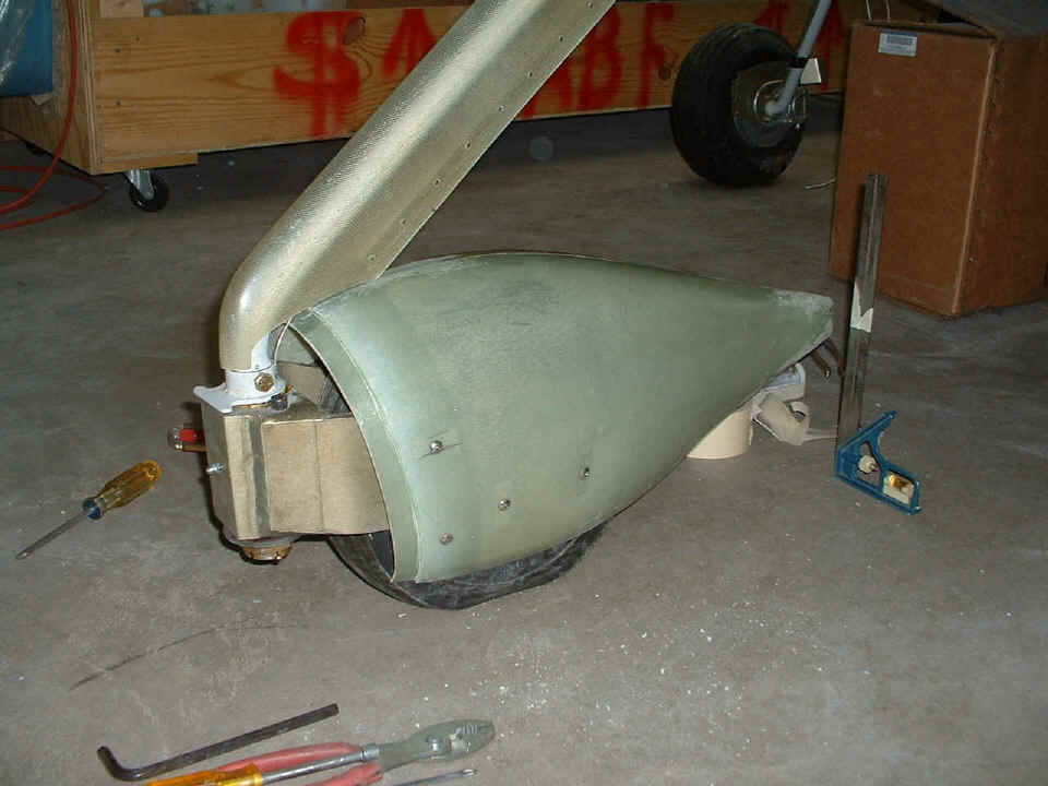
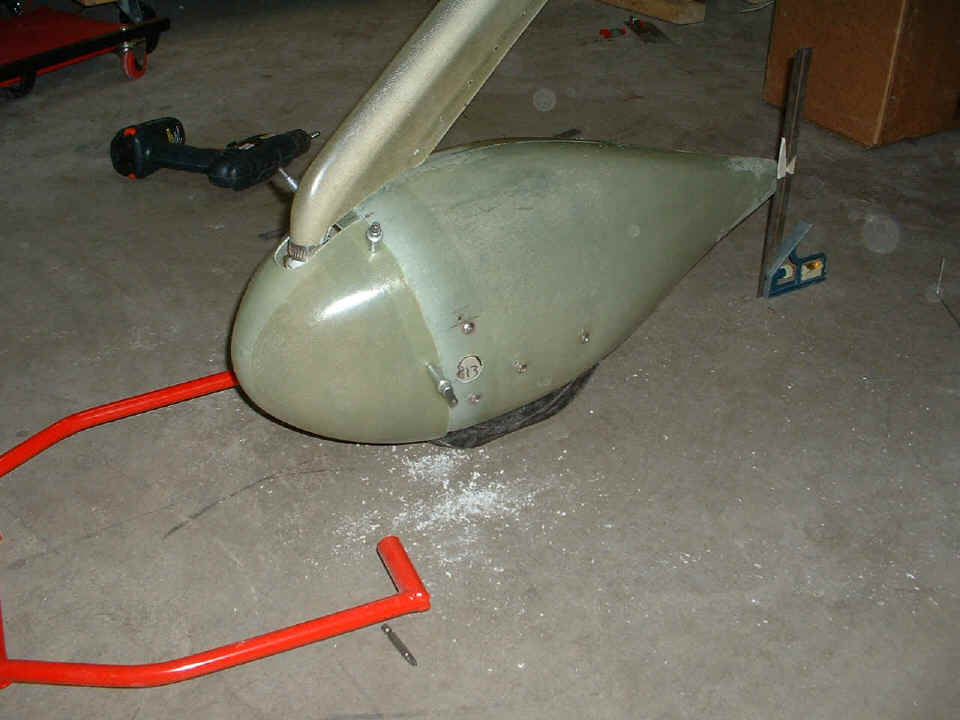
Once I had determined how many ways this affected my situation, I realized I
can easily fill and repair the extra holes, so I drilled new holes in the correct
positions. Here is the result. Compare the amount of space between the nose
piece and the gear leg where it goes down to the yoke in the two photos posted
today.
I also drilled and sanded the access holes for the tow bar. The gear leg
fairing got some extra trimming at the top end, and I may have to trim a bit at the lower
end when I get the lower gear leg fairing ready to go on the nose piece. I have to
install SIX platenuts to hold the nose piece to the wheel fairing in my next session.
I removed the lower cowl to prepare for the installation of platenuts that will
secure the upper intersection fairing for the nose gear leg.
| CLICK HERE for Finishing PAGE 106. | RETURN to MAIN MENU. |