FINISHING - Page 87.
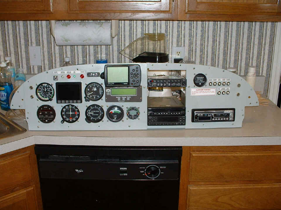
January 20, 2005: I also got the panel fully
assembled with the radio stack for the first time and figured out how to get the
headphone/microphone jacks into the proper location. The photo below shows
everything in
position before making the changes to the audio jacks at each side of the panels.
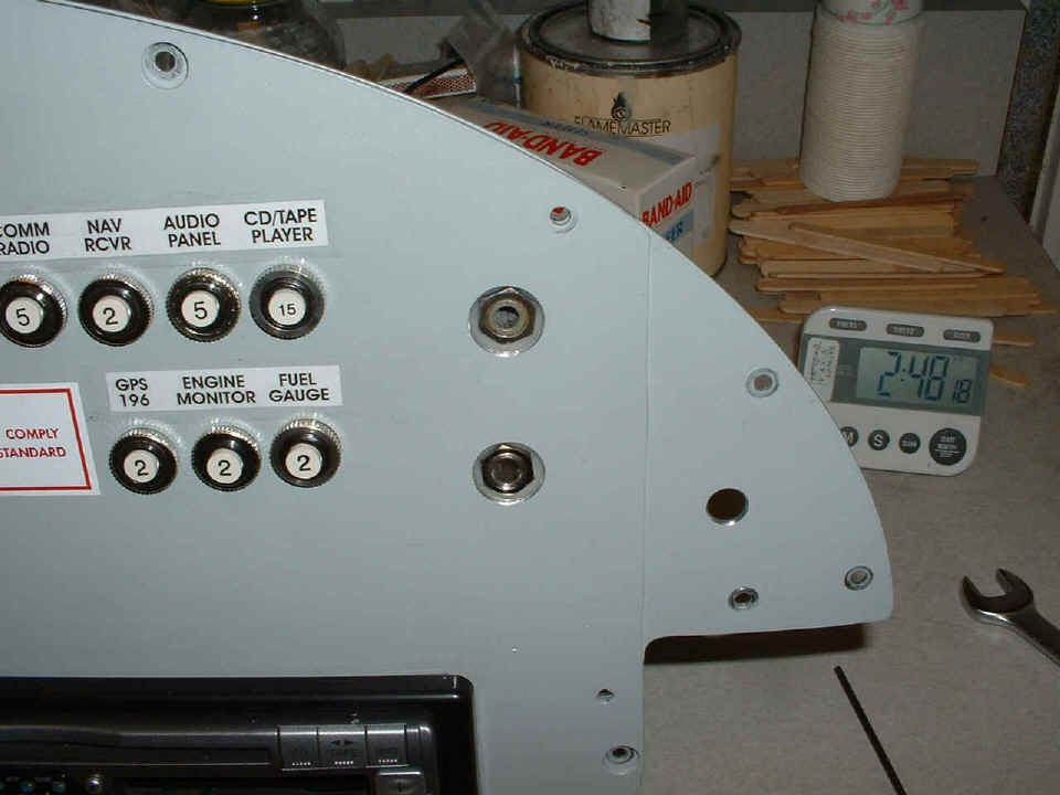
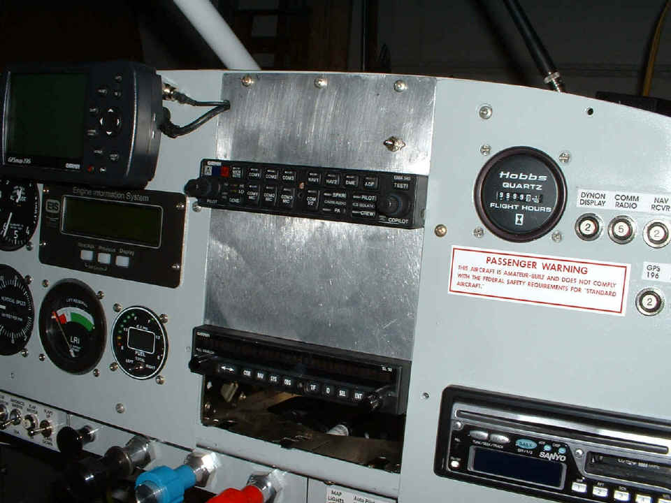
This is how they looked after the modifications. The holes on the front
removable panels are now two unibit sizes larger than before to clear the mounting nuts
for the jacks. The nylon insulating washers are in the space behind the front panel
and the mounting plates for the jacks. This was a good lesson in back drilling and
using the unibit successfully. You are seeing one side of the two nylon insulating
washers around the nuts that hold the jacks in place. The nut is in the same plane
as the removable front panel. The holes in the front panels had to be large enough
to clear the nuts to prevent a ground loop that could introduce noise into the audio
channels.
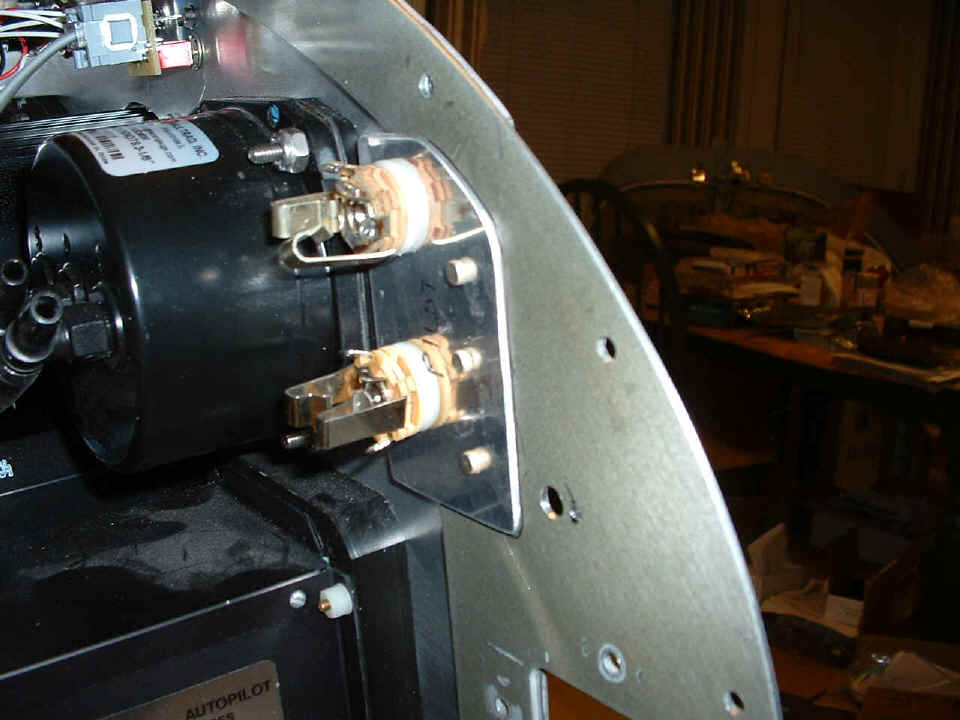
This is how the jacks look on the back side of the panel frame. Three
number 4-5 flat head rivets hold each 0.063" aluminum mounting plate to the panel
frame. A second nylon washer is on this side of the 0.063" aluminum plate to
insulate from ground at the panel. I had to cut the corners of the plates to clear
rivet strips that will hold the forward top skin in place later in the construction.
The nice part of this modification is that the harness will not be disturbed when
it is finally put in place. I will wire them now for testing, but will remove the
jacks and let them hang by their wires when the forward top skin is finally riveted in
place. I will be able to remove the front instrument panels for servicing anything
in the panel without disturbing the microphone and headphone jacks.
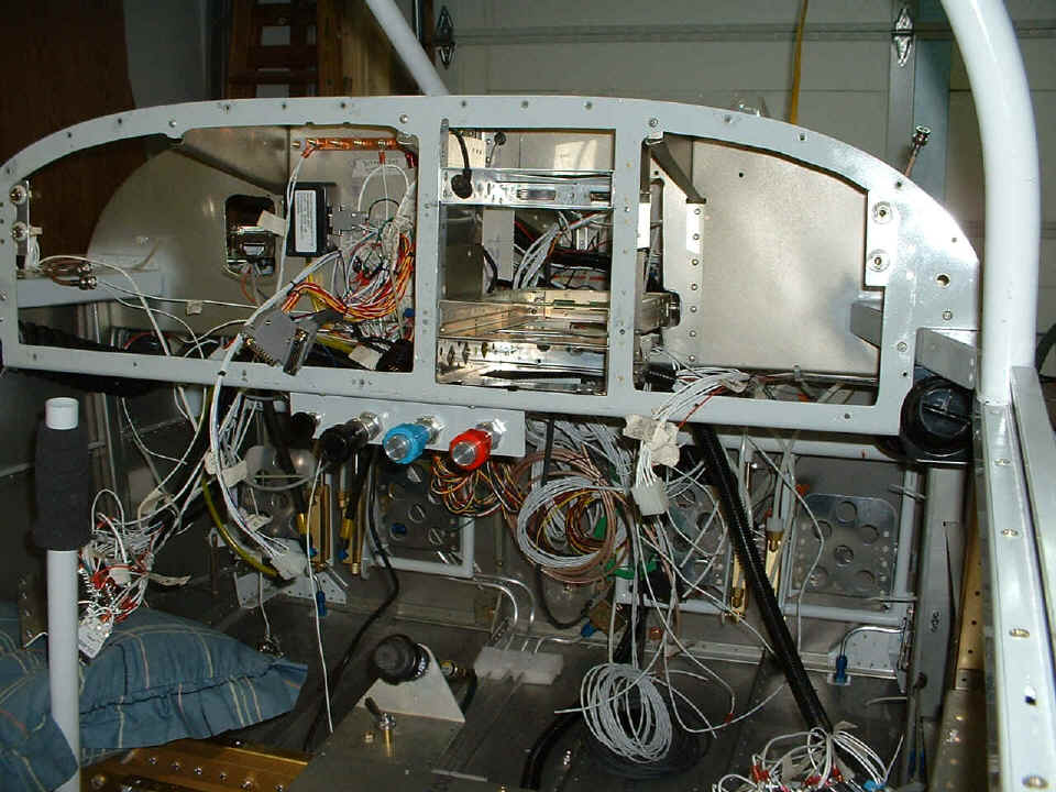
And the stopping point for the evening was the relocation of the panel frame to
the fuselage. Now I can begin to get EVERYTHING wired from the audio panel to the
phone jacks, from the stereo player to the audio panel, antennas for the radios and radar
transponder, and the power connections to the various circuit breakers that are already in
place in the panels. The LEFT and RIGHT switch and breaker panels are laying on
pillows on the wing spar just below the picture. You can see that I have secured the
throttle quadrant to the frame, and the frame is secured on both sides and to the three
ribs up top. Next time we make things really start to work.
January 21, 2005: Some clean up work of the firewall, replacing a plastic plug with a metal one in an unused sensor wire hole that proved to be too close to the ignition control cables. The B+ wires to the new avionics were connected via Molex connectors to the proper circuit breaker locations on the RIGHT panel. I ran the wires to all headset jacks from the audio panel. I also cut and cleaned the blank panels that go into the radio stack above and below the GMA-340 audio panel. Wiring is kind of dull, so no photos today.
January 22, 2005: Saturday's are always good
to catch up on much stuff. This is the blank panel that goes above the Garmin
GMA-340 audio panel. I had to put both the LEFT and RIGHT panels back into the panel
frame in order to mark the locations of the mounting holes and the notch in the panel
frame for the GPS cables.
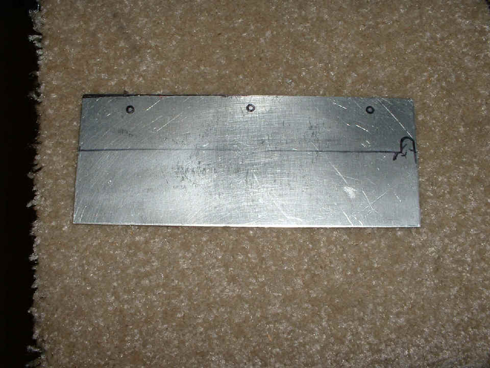
After drilling that plate, I had to cut out the notch to the SIDE toward the
GPS to hold the data/power cable and antenna cable in place when this blank panel is
secured. The speaker selector switch is the only thing in the blank panel above the
audio panel. Nothing is connected to it at this time. The blank panel below
the audio panel is the size of the Garmin GNS-480 panel-mounted GPS/COM/NAV unit that I
hope to acquire some day as an approach approved GPS navigation unit. If the weather
permits it, I will paint both blank radio stack panels tomorrow, and wire up the speakers
to the CD/Tape player stereo and the audio panel. This will be the only way to play
music for now.
I went to the local electronics store around noon today to get some male pins
for D-sub connectors on the back of the audio panel. It turns out there are two
kinds, and of course, I got the wrong size. It seems that D-sub connectors that have
three rows of pins use pins with a shank diameter of approximately 0.060". The
more popular pin size for DB-9, DB-15, DB-25 connectors has a shank diameter around
0.082". Needless to say, the size I needed was the 0.060" for the
input/output connections to the Garmin audio panel. The audio connections from LINE
OUT of the stereo player cannot be made until I get the 0.060" male pins to fit the
44-pin D-sub connectors on the audio panel. So no stereo music in the headphones for
now. As you can see below, I got out both of my aviation headsets and plugged them
into the panel jacks. I had to swap two wires on the microphone jacks to get
everything going.
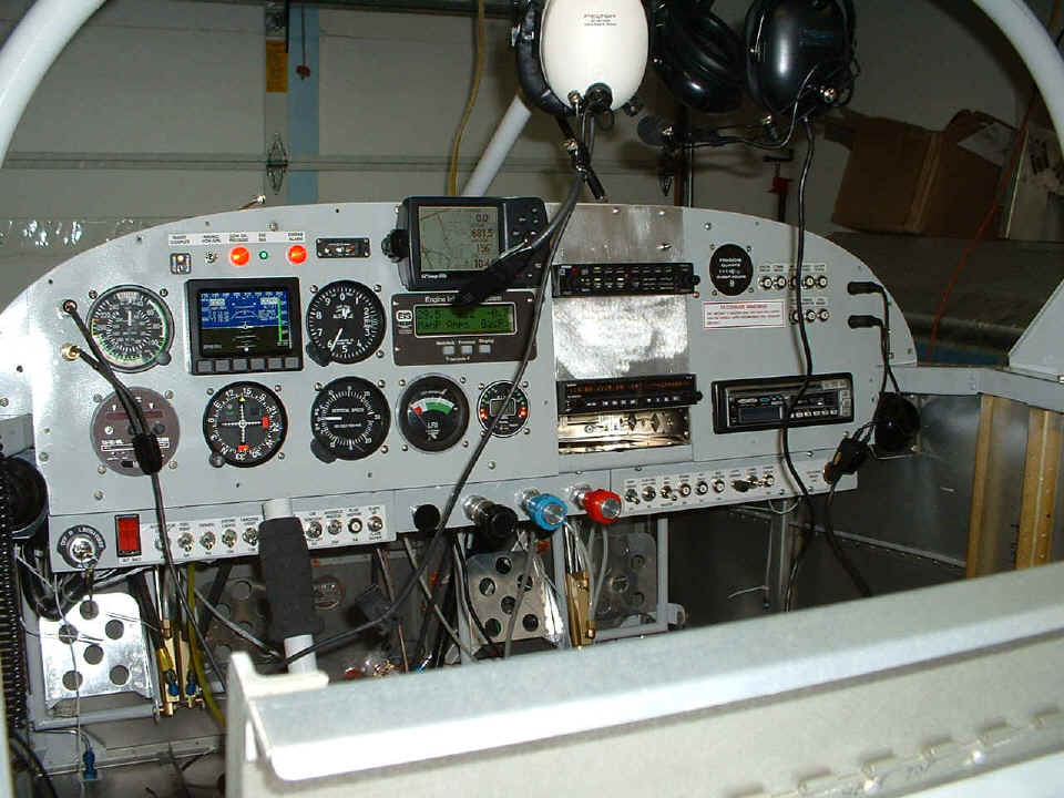
Here is the shot from the kitchen door to show you how I had things hooked up
to test the NAV/COM radio and audio panel. I clamped the communications antenna to
the top skin and ran the coax through the cabin just to listen to the ATIS, tower, and
approach at the Chattanooga airport which is nearby. I can also receive Atlanta
Center on two frequencies from a mountain top about 16 miles from here. I put a
rubber ducky antenna on the coax cable to the NAV side of my SL-30 receiver to tune in the
Choo-Choo VOR (GQO, 115.8 MHz) which is about 3 miles from my
place and managed to receive signals occasionally to check the OBS operation.
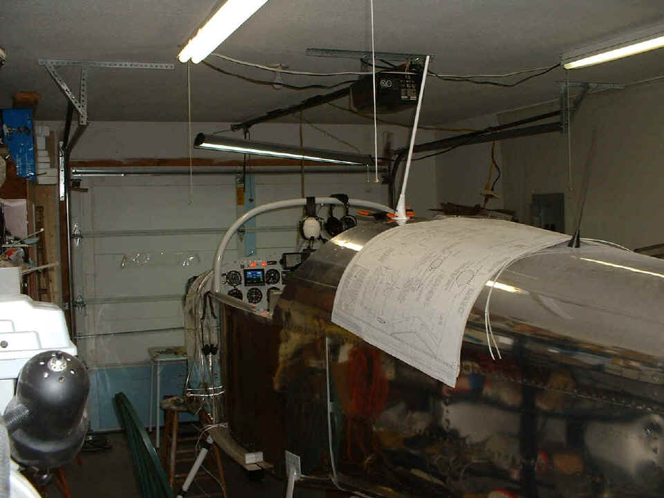
I also found the Push-to-Talk (PTT) green wires from the harness were not labeled like all the other wires. I used my volt-ohm-meter to identify which went to the pilot and copilot and routed the wires to the correct locations. I will get a chance to wire them up to the joysticks tomorrow. I will probably put in the antennas for the 75 MHz marker beacon receiver, radar transponder, and the com antenna you see clamped onto the top skin. All three of those antennas will go on the bottom of the airplane. Only the black ELT antenna that you see in this picture and the VOR antenna that goes at the top of the vertical stabilizer will be mounted on the top of the airplane. I took the VOR antenna off the vertical stabilizer in my living room and removed the cable from the tail in order to verify that I could thread both coaxial cables for the VOR and marker beacon antennas through the bushings in the elevator push rod tunnel between the seats. They fit fine after I moved one 16 gauge wire that powers the strobe power supply to the other bushings that pass the elevator trim cable up that same tunnel on the other side of the elevator push rod itself.
Add 7.0 hours to the construction log book for today. That gives a total of 1577.7 hours of construction including some hours today learning the computer sub-routines that operate the Garmin SL-30 NAV/COM radio.
| CLICK HERE for Finishing Page 88. | RETURN to MAIN MENU. |