FINISHING - Page 88.
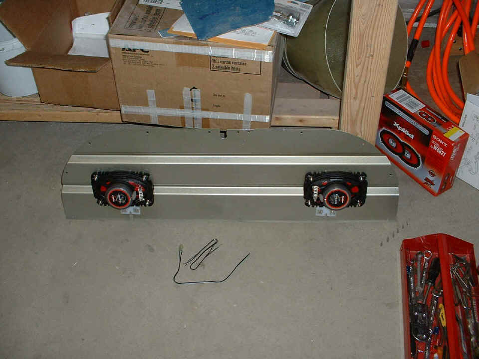
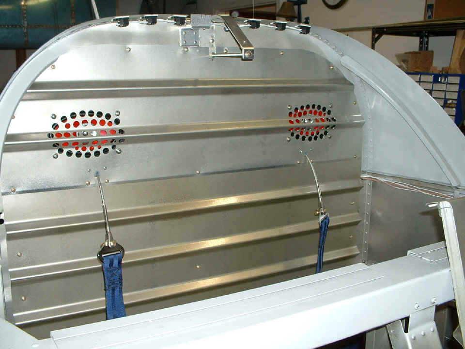
January 23, 2005: The 4x6-inch Sony stereo
speakers were mounted after I picked up some additional hardware at the local Ace Hardware
store. This is the upper baggage bulkhead panel seen from the back side. There is a pattern of 1/2" holes and slightly smaller sizes on the
other side of the speaker cones. I placed these as far apart as possible and
still be able to clear the bulkheads that hold the panel in position. The wires with
spade lug terminals on the floor came with the speakers and will need to be spliced to the
Tefzel wire I am running from the speaker control switch above the audio panel. The
switch is a triple-pole double-throw (TPDT) switch that will switch the LEFT speaker to
the audio panel output (mono), or connect both speakers to the CD/Tape player. The
third pole on the switch will open ONE wire to the right speaker in the CENTER and LEFT
positions. The other two poles of the switch will connect directly to the LEFT
speaker on the common terminals since the car stereo does NOT use a common ground for the
speaker circuits. The CENTER position of the switch will silence the speakers, the
LEFT position of the switch will connect the LEFT speaker only to the audio panel output,
and the RIGHT position of the switch will activate BOTH speakers from the stereo
amplifiers of the CD/Tape Player. When I get the infamous D-sub pins, the Music 1
input to the audio panel will provide tunes to the headphones during flight. The
speakers are only intended for ground use, like at fly-ins, fuel stops, etc. The
sound system will work through the speakers without the master switch being ON. It
has its own circuit breaker tied directly to the battery bus.
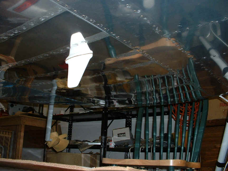
I put the 75 MHz marker beacon antenna on the underside of the tail cone and
connected it to the BNC fitting and cable that runs back to the marker beacon receiver in
the audio panel. I used 2-inch wide masking tape to hold it in position while I
climbed inside and engaged the mounting screws and the BNC RF connector. I may have
to enlarge one of the holes after I saw this picture in detail. There is a tuning
element on the top side of the antenna assembly that appears to be deforming the aluminum
sheet metal here. I feel that hole needs to be about 1/32" larger to clear that
tuning slug. Looking at the picture below, can you tell where the mounting screws
are located? Isn't it the luck that the RAMI label is more legible in the reflection
than in the direct image due to the glare from the camera flash.
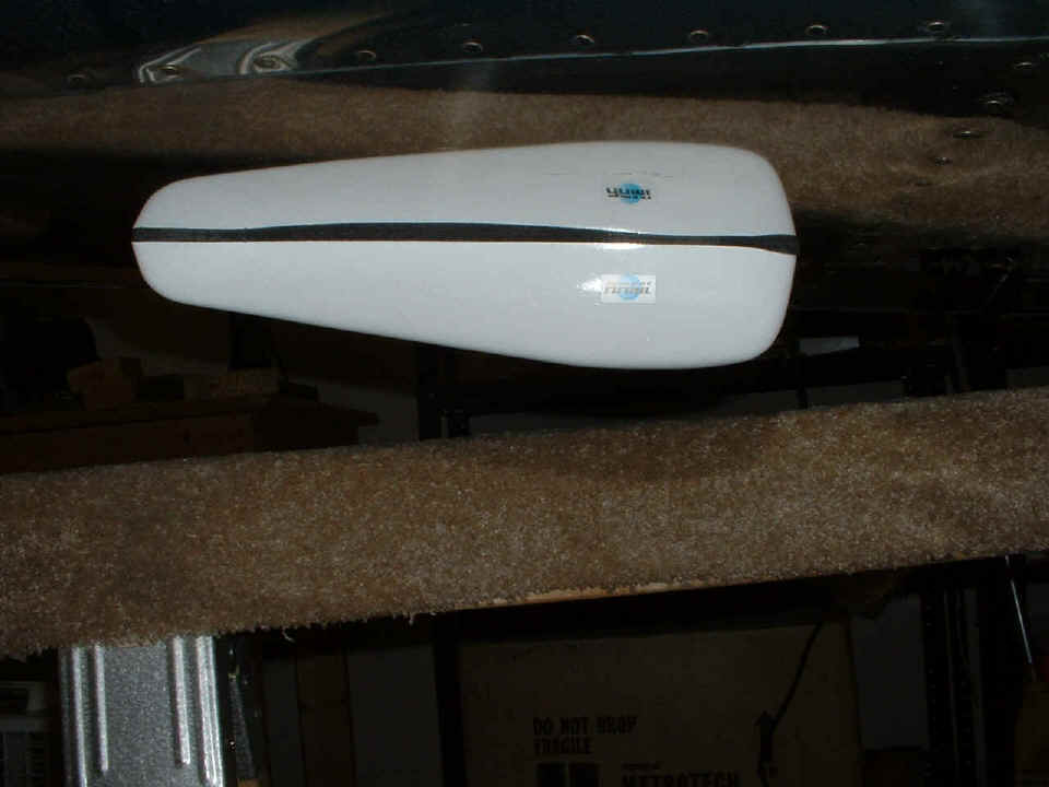
And just so you know, the saw horse is just stored under there, it is not
supporting anything.
January 24, 2005: Tonight I was inside the aft
fuselage again putting the doubler plate, lock washers, and nuts on the communications
antenna. It has replaced the ELT antenna at the location just behind the sliding
canopy. The ELT antenna has moved just aft of the F-708 bulkhead. I also took
off the marker beacon antenna and enlarged the tuning hole for proper clearance before
securing the antenna again.
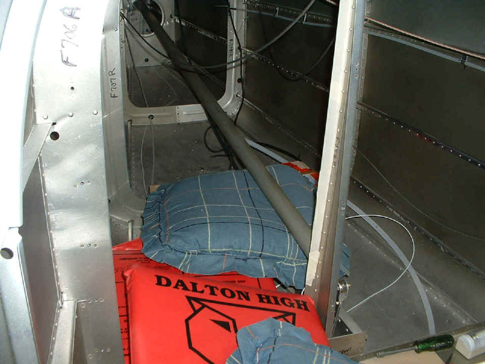
Here is the way I get inside the tail cone area. Pillows and cushions on
some of the salvaged boards from Van's shipping crates. You can see the beige RG-400
coaxial cable on the right side of the fuselage near the static air line. I opened
up the holes in the bulkheads that had been passing only the static line to a size of
5/8". That hole size is big enough to pass a BNC connector through it. I
can then put in a 5/8" plastic bushing by cutting a slit on one side only.
After that, the diameter of the coax is small enough to pass the static air line through
and some speaker wires for the rear speakers. That solved some issues with trying to
get too many wires through the two bushings in the elevator push rod tunnel.
The other accomplishment tonight was the audio connections from the line out ports of the CD/TAPE player to the MUSIC 1 input of the Garmin GMA-340 audio panel. I also connected a pair of wires to inhibit the "music mute on intercom" function. I drilling a new hole for mounting a switch to handle that function in the blank panel above the audio panel. I scrubbed both blank panels with a Scotchbrite pad and dish detergent before painting them as the last job of the night. We get to see them tomorrow when they are completely dry and I put on the switches and labels.
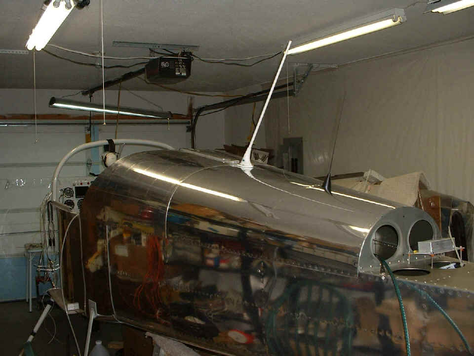
January 25, 2005: This evening the focus was
on audio via the speakers and then installing the radar transponder antenna. I put both the
baggage bulkhead panels in place after I finished running the speaker wires from the
CD/Tape player to the speaker control switch, then to the speakers themselves. You
can see the wires and the RG-400 coaxial cable for the communications antenna at the right
side of the picture. I will have to remove these wires and the coax from that area
when it is time to rivet on the front top skin and put them back after the riveting is
completed. They would be in the way of the bucking bar near the windshield roll bar
and the instrument panel. I will secure the wires and cable when the riveting is
finished.
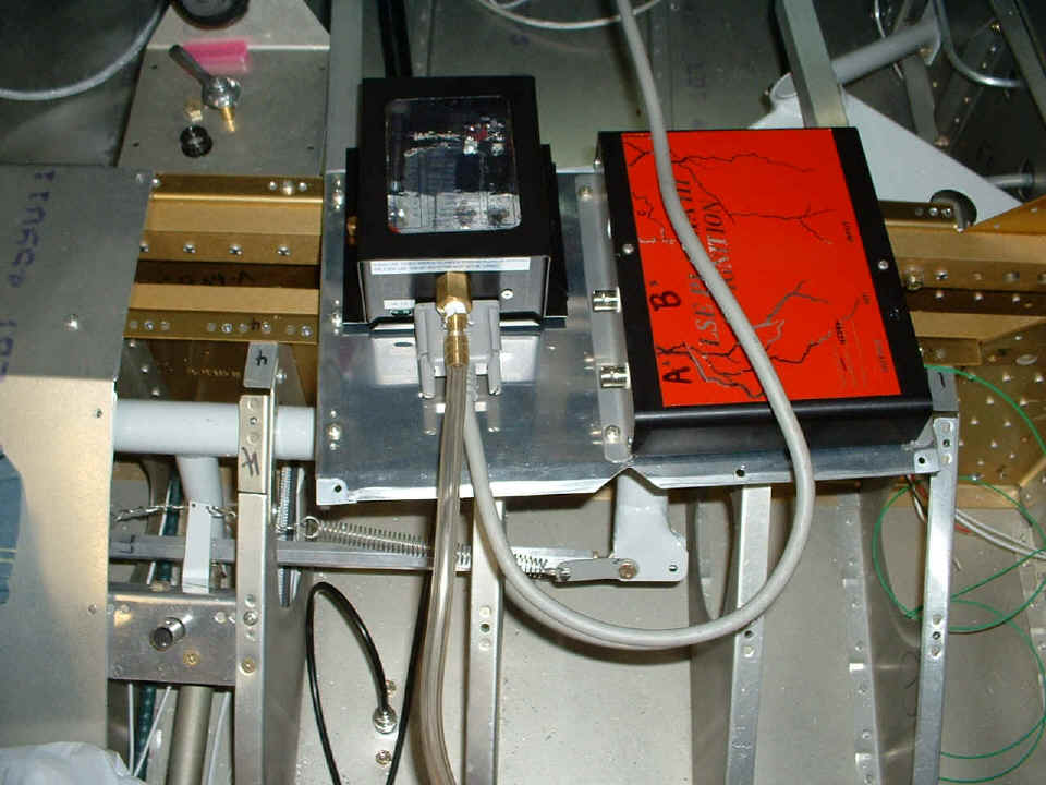
Here is the radar transponder antenna on the belly of the fuselage between some
seat ribs. You can also see one of the steel steps to climb on the wings when they
are put on at the airport. For now, that wooden chair is my step up into the cabin
area.
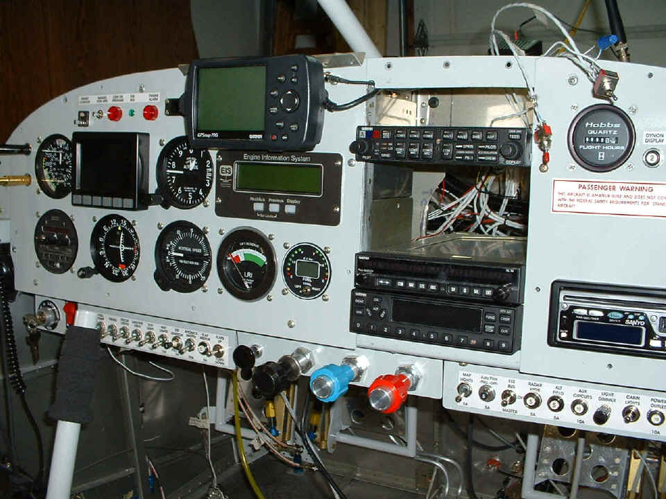
At last everything is in place in the panel except for the blank panels in the
radio stack. I tested the transponder and found the altitude encoder was doing its
thing. The GTX-327 can display the data from the altitude encoder on the LCD screen.
I tried the LEFT speaker on the audio panel and got a feedback issue that is
probably a ground loop. I also noticed that the intercom music mute inhibit is not
working now. I removed the audio panel and saw that the pins I put in seem to be
smaller than the pins that came with the GMA-340. I discovered this around 6:30 PM
and quickly called Pacific Coast Avionics and mentioned this to their avionics technician.
He is sending me some pins that are identical to the ones he installed before
shipping the units to me. Pacific Coast Avionics is across the airport from Van's
Aircraft.
I used my unibit to open up a 5/8" hole in both of the carry through
spars at a point that did not interfere with fuel lines, rib flanges, or the aileron
linkage between the joy sticks. I have put in some plastic bushings, but will do
more to prevent the cable from vibrating around. You can see the BNC connector and
both mounting screws on the antenna at the bottom of the picture. That green wire is
the push-to-talk line for the COM radio. I suppose I will have to tackle the wiring
on the stick grips in the next session.
After the stick grips are wired, the insulation for the firewall should be one of the last
things to do before putting the forward top skin in place. The last thing of course
would be to reinstall the panel you see in the photo above with the removable encoder and
solid state ignition control module on it. Let's move on to Finishing - Page 89.
| CLICK HERE for Finishing Page 89. | RETURN to MAIN MENU. |