FINISHING - Page 83.
January 8, 2005: After a lunch break and a
run for more crimp ring terminals, I went back to work on the airplane wiring. I
finally got to the point of wiring up the power and ground connections to the dual fuel
gauge and the GRT EIS. The first item on the list of things to connect to the EIS is
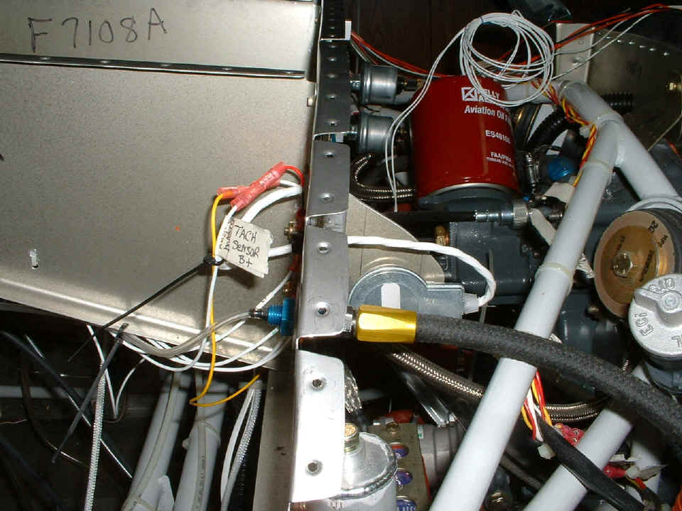
the tachometer sensor. Since David Edgemon has this same unit, I called him to
discover the shortcuts. I drilled a hole in the firewall at the appropriate place
and installed a 1/4" black plastic bushing. The sensor cable was passed through
and the connections to B+, ground, and the yellow wire to pulse the EIS were quickly made.
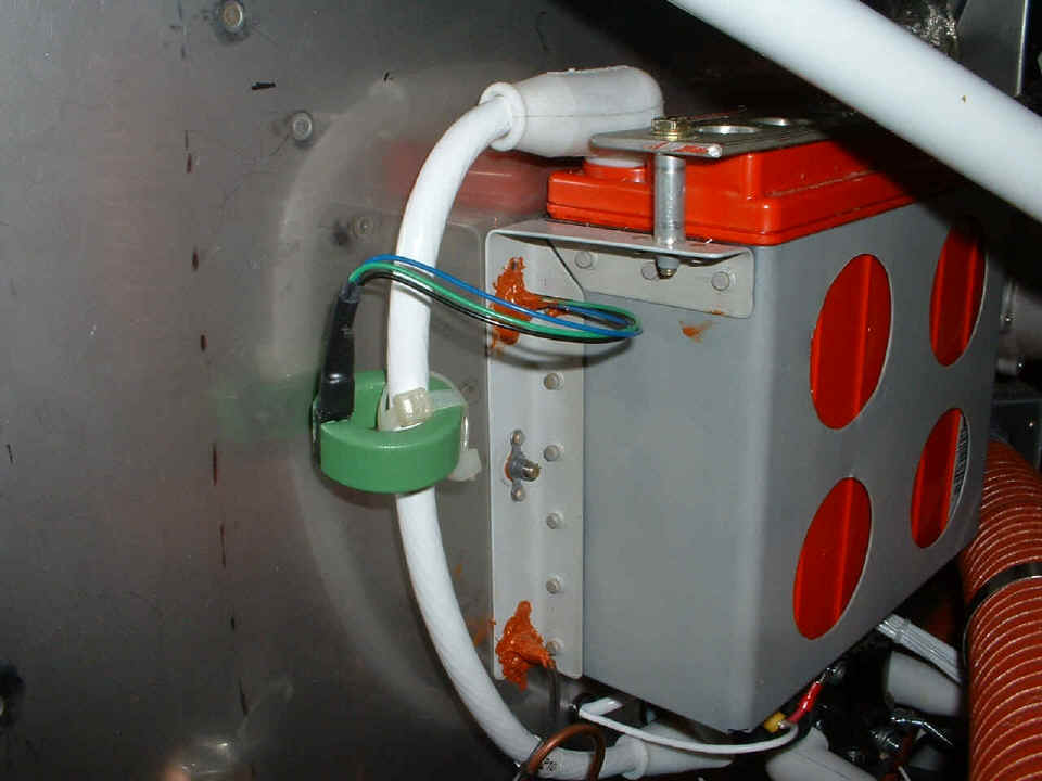
Down by the battery, the current sensor was the next thing to do. I had
drilled some extra holes in error when I was mounting the battery box. Those holes
became useful for the engine primer valve, and now for the current probe. I used
plenty of RED high-temp RTV to seal the holes and the wires. I pumped each of the
three wires gently back and forth through the hole coating all three wires with the
RED RTV,
keeping them from vibrating against the firewall or each other. A similar
"glob" of RTV is on the inside of the firewall. I had to use a razor
scraper to get "some" of the RED RTV off the inside from the first time I sealed
the hole several months ago. It is tough stuff, and should protect the wires and
seal out any fumes from the engine if there should be any inside the cowling. I
finally used my pocket screw driver to punch through the old RTV to slide the three wires
through the hole and put on the new coat of RTV. There are two more holes below the
battery that will also need the RTV treatment.
When I am fresh tomorrow, I will continue to wire up the sensors to the GRT EIS. I have sensors for manifold pressure, oil pressure, oil temp, fuel pressure, fuel flow, and amp meter (current probe shown above) awaiting connection to the unit on the panel. All EGT and CHT connections are already made.
The construction time now stands at 1509.6 hours after two work sessions from this day - Saturday, January 8th, 2005.
January 9, 2005: What can I say? This
was a GOOD DAY! A milestone day to be sure. I
worked 10.2 hours today in two sessions and got everything wired that is on hand except
for the eyeball lights. This was early in the day when I started wiring up the
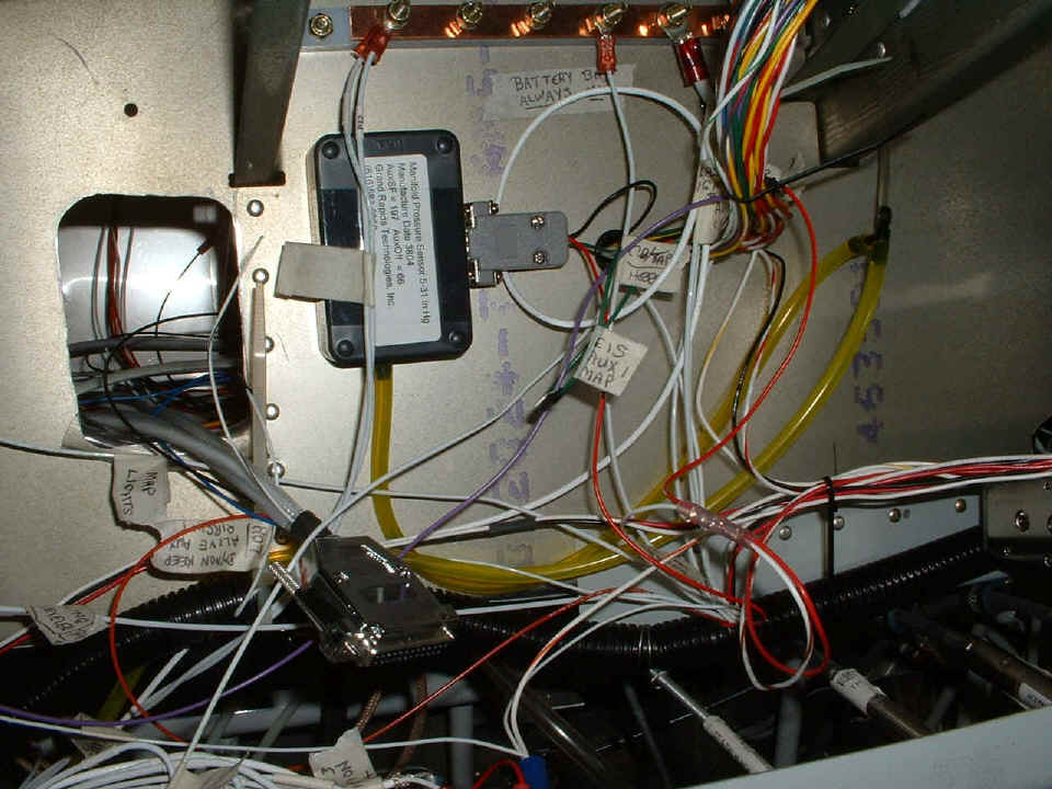
remaining sensors for the Grand Rapids Technologies Engine Information System (EIS).
This black box is the manifold pressure (MAP) sensor stuck on with double-sided thick foam
tape. I had to run out for a barrier strip and some mounting hardware to get some of
the other sensors wired. I ended up putting the barrier strip just below and to the
right of the MAP.
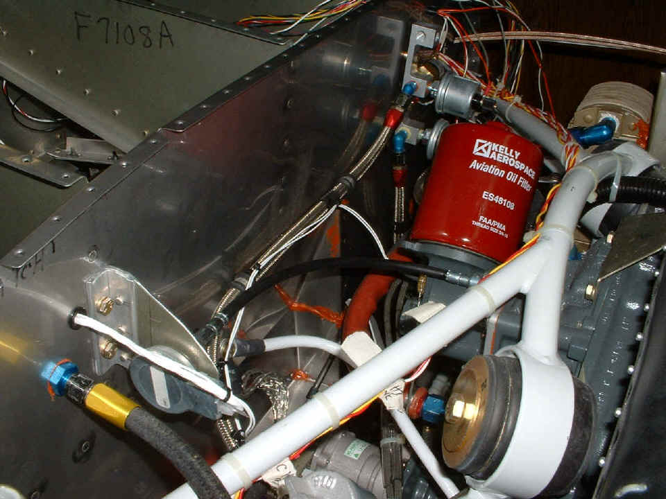
The more I got into this, the more I wanted to get it all done today. The
two white wires coming from beneath the oil filter are from the oil temperature probe.
I ran them along with the oil pressure sensor line and entered the firewall at the
same point the tachometer sensor wires go through.
Just a few minutes before midnight, the lights all came on when I flipped the
master switch and the avionics master breaker. This photo was flashed as you can see
by the reflection. The big RED light on the panel will always be on when the master
switch is ON and there is no oil pressure. The GREEN LED light is on when the
essential bus optional items are working. The 20-ampere avionics master
switched-circuit breaker and the essential bus toggle switch are tied directly to the
battery. The RED I.ED lights on the dual fuel gauge were also flashing, but the
timing of the camera shutter caught them in the OFF condition. The master switch
runs all the exterior lights, strobes, and the alternator field current via appropriate
switched-circuit breakers and conventional circuit breakers. The various avionics
devices have individual circuit breakers. The lift reserve indicator (LRI) is
totally passive, operated only by air pressure, same as the airspeed, altimeter, and
vertical speed indicator.
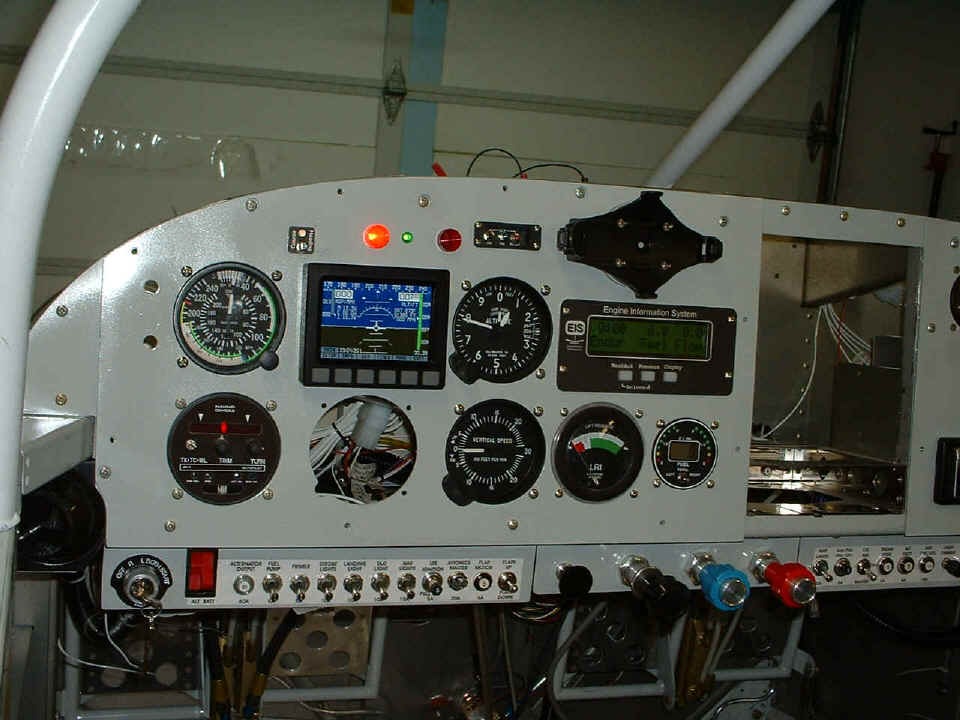
I have not plugged in the radar transponder since the antenna is not yet mounted or the coaxial cable installed. I am waiting for the audio panel, and the NAV/COM radio to arrive some time this month to build the radio stack. The switch and LED (dark) at the upper left corner of the Dynon unit is the control and indicator LED for the Smart Coupler built into the Nav-Aid Devices wing leveler/auto pilot. The Smart Coupler uses serial output data from my Garmin GPS 196 to track a course programmed into the GPS. That missing item under the Dynon unit will be the indicator for the VOR/ILS/GS output from the Garmin SL-30 NAV side of the NAV/COM receiver.
I have used up virtually all my Tefzel wire and will have to order more, along with a few more circuit breakers to get everything properly isolated on the power bus. I also have to start learning the software routines and programming the EIS unit sensors and editing the pages that I want to customize in its various displays.
January 10, 2005: I spent about two hours
just sitting in the left seat getting to know the GRT EIS sub-routines and programming in
the information it needs to function correctly. When it finally stopped asking me
for more data, I played with the normal monitoring screens and then went to work on the
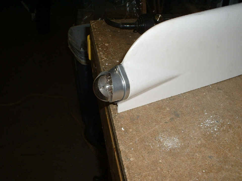
tail light in the rudder bottom cap. Here is the final result in today's single
photo for this posting. I used my Dremel sanding drum again to take away the excess
mixture of tissue and epoxy allowing the body of the light fixture to fit properly.
Then I got out my drill and 4-40 tap to work on the screw holes. It worked just
fine! I may put in longer screws in the final fit, but it seems secure now. I
just want to be sure it can withstand plenty of vibrational stress. The other little
thing today was the trial fitting of the joy stick grip on the pilot's side. It
fits nicely and does not bump into the instrument panel. That means I won't have to
shorten the control sticks.
I placed my order with Spruce for circuit breakers, more Tefzel wire, and the data/power cable needed for the GPS 196 to interface with the Nav-Aid autopilot. All of it shipped today from their Eastern warehouse near Atlanta and will arrive at my place tomorrow. I will keep you posted on that stuff when it goes into the airplane. And yes, I will remove the tail light since the outer clear lens is made of GLASS, not plastic. It goes back in the padded box until final assembly at the airport.
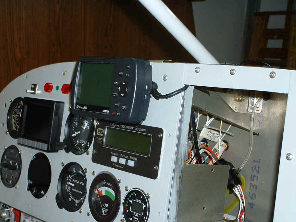
January 11, 2005: The package from Spruce
arrived and tonight I starting installing the Garmin data/power cable. I got it
secured as it passes through the front of the panel above the radio stack. I tied it
off along the conduit that runs across the bulkhead behind the panel. I have it
secured near the Nav-Aid autopilot control head, ready to make the serial data connection
there. In the photo below, the cable goes inside the panel and over the top of the
left mounting rail/angle and tie-wrapped there. When I have filled the radio stack,
I will cut a blank panel to go there with a notch at the correct location to pass the
cable. That blank panel will be secured to the three screws you see above the stack
area. I had even considered cutting a notch in the back panel above where you see
the cable now, if I need that extra 1/4" of vertical rack space. The GPS
antenna cable is not connected in this photo. It will also have to go through the
panel alongside the data/power cable.
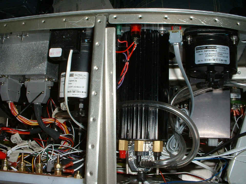
Behind the panel, things are getting crowded as you can see looking down from
above. I have some clean up to do back there and then tie-wrap the various wire
bundles into the proper groupings. The top of the image below is the panel
facing the pilot seat.
I spent another two hours getting familiar with the programming of the GRT EIS unit and managed to put in my desired labels for my three auxiliary sensor inputs, and turned off the pages that I did not want to display. While I was testing the unit, I compared some readings with the air gauges and the Dynon sensors. I set the passive altimeter to altitude ZERO and the Kollisman window displayed the true air pressure in inches of mercury, which is approximately 29.4" at 700 feet above sea level here near Chattanooga. The GRT EIS and the passive altimeter agree. Of course the GRT EIS will be measuring engine manifold pressure with its sensor.
I have thought of some wiring changes that need to be made to the panel, and have the circuit breakers now to do that. I also put in a slightly longer bolt at my firewall grounding point for all the avionics, and moved the Dynon ground cable to that location. The only things not grounded there are the CD/tape player unit and the tachometer sender.
That finishes up this page with EIGHT pictures for you dial-up users. And yes, the tail light is now safely back in the padded box that Whelen provided for shipping. Next session, we begin page 84!
| CLICK HERE for Finishing - Page 84. | RETURN to MAIN MENU. |