FINISHING - Page 84.
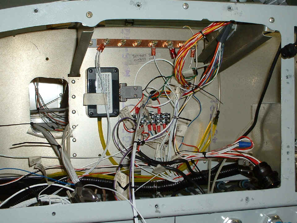
January 12, 2005: The stuff that came
yesterday has made its mark on my evening's work. Here is that look behind the panel
again showing how the barrier strip got loaded up. I have regulated voltage from the
GRT EIS unit and B+ from the AVIONICS MASTER on this strip driving other sensors.
Don't get excited about that BLUE wire nut, it is just temporary until I get the panel
illumination lights wired in permanently. That will be coming up when the panels get
back in place. After seeing that rat's nest from page 83 behind the panel, I wanted
to get things tied up a bit before moving on. One of the things in that mess near
the barrier strip is the Garmin data/power cable. I cut into it to connect the power
wire to the avionics bus, to provide a second data output line and ground wire to the
autopilot, and continued both data lines to a DB-9 connector for computer connections.
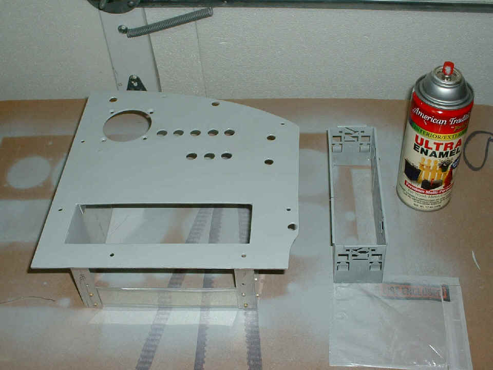
I was very careful to drill my extra holes in the RIGHT panel for the three
extra circuit breakers from the BACK SIDE so as not to scratch the paint, but it got
scratched anyway. Before I painted over the scratches, the labels had to come off
and I also improved the fit and finish of the stereo mounting kit.
I mounted a DPDT switch on the LEFT side of the panel frame near the NavAid controller. It will select whether the guidance is from the GPS or the VOR/ILS receiver. I also touched up the paint on the LEFT panel near the Smart Coupler control switch and L.E.D. indicator. I am going to wait a few days for paint to dry on the panels and will be cleaning up the wiring on the engine mount with some silicone tape for chafe control.
January 13, 2005: This was a milestone day for SURE!!! The word from Van's is GOOD! My avionics order shipped yesterday. I noticed a charge for it to my Visa card online with my bank, then sent an email to Van's order department. The reply came around 11 AM Eastern time (8 AM Pacific) with a FEDEX tracking number. The package is due here on Tuesday, January 18th.
My work on the airplane tonight was also a milestone
session. That panel in the photo above is now reassembled with all eight circuit
breakers in it and the labels are in place. The wiring to the DPDT switch for the
NavAid autopilot is completed via the 12-pin Molex connector that powers the warning
lights on the LEFT panel. I fired everything up and verified the GPS 196 was talking
to the digital Smart Coupler built into the NavAid unit. The steady GREEN L.E.D.
above the Dynon unit said everything is JUST FINE! Tomorrow, I will get my laptop
computer in the airplane and run it from the 12-volt accessory outlet and verify that I
wired the RS-232 DB-9 plug correctly with a map program I use in the car with the GPS 196.
It is time to create the labels for the warning lights and the autopilot source
selector switch.
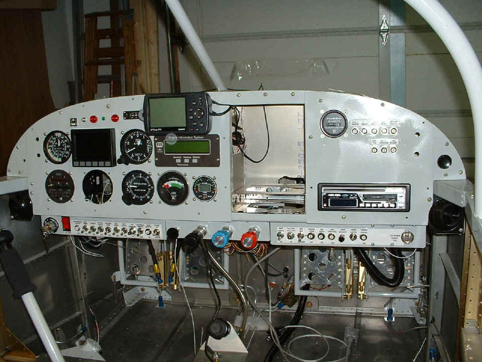
There is a 1/4" hole in the original instrument panel (frame) at the far left
side. Yesterday I thought I would have to put the DPDT selector switch for the
autopilot there, but I worked out a way to put the switch just to the left of the RED
warning light that is centered above the Dynon unit. Now I have to decide how I want
to fill or use the extra hole in the panel frame. The two holes on each side of the
panel are for headphones.
When the box from Van's Aircraft arrives next week, I get to integrate the wiring harness for the headphones, the wires from the NAV receiver to the OBS/VOR/GS/ILS indicator, and the antenna wires to their respective locations in the fuselage. I also have to run the wires from the push-to-talk buttons to the appropriate connections. After that, I can try out some of that stuff, including the stereo CD/Tape player via the audio panel and my headphones. I have a handheld NAV/COM unit from Sporty's and I can actually receive the Choo-Choo VOR (GQO, 115.8 MHz) here at the house on the ground floor in my living room adjacent to the garage. The airplane should also receive the signal when everything is operational.
January 14, 2005: A short session due to
Friday night groceries and other out of the house chores to do. In the short session
early in the evening, I secured the oil filler tube to the engine crankcase properly with
safety wire properly twisted. The new safety wire wraps around the filler tube about
300+ degrees before going to the tie point on the crank case. That other painted
safety wire came from Penn Yan Aero holding the oil filler tube extension in place.
Those EGT/CHT wires you see tie-wrapped to the mount are one of the reasons I went
shopping for more clamps tonight.
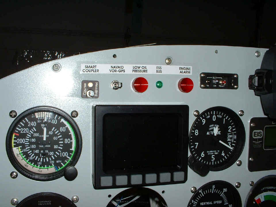
The other visible work this evening was the label strip for the warning lights
and autopilot controls. The ELT test console had labels already. The LOW OIL
PRESSURE light is the one tied directly to the oil pressure/Hobbs switch. The ENGINE
ALARM could be any of the many alarms that can be programmed into the GRT EIS unit.
The items procured tonight included clamps and stainless steel bolts to secure various wires on the engine mount, batteries for the ELT, and speakers for the stereo. I know I said I would not be getting any, but there were these Sony speakers that would fit nicely out of the way under the panel for those times when I am on the ground working in the hangar with the charger on the battery (blah, blah, blah). I have to get another DPDT switch to turn off the speakers except for ground usage. I may actually have to get an AM/FM antenna for this thing yet.
January 15, 2005: Time to finish up this
page with today's report. Saturday's are good days with lots of time to work on the
airplane. The work today was 7.4 hours in ONE session. I bought a suitable
switch to turn off the stereo speakers and I put it into the extra hole that I had drilled
on the left side of the main panel. I then started cleaning up all the cable
placement on the engine mount for the EGT and CHT connections, the two RG-400 high-voltage
control cables, and the "P-Lead" to the LEFT MAG. My battery charger is at
the top of the photo plugged into that yellow extension cord.
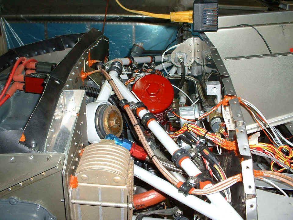
You can see all the clamps I bought yesterday have been used to secure the
cables in a way that will not vibrate against anything else. I even used silicone
tape to insure the clamps would stay tight against the steel tubes of the engine mount.
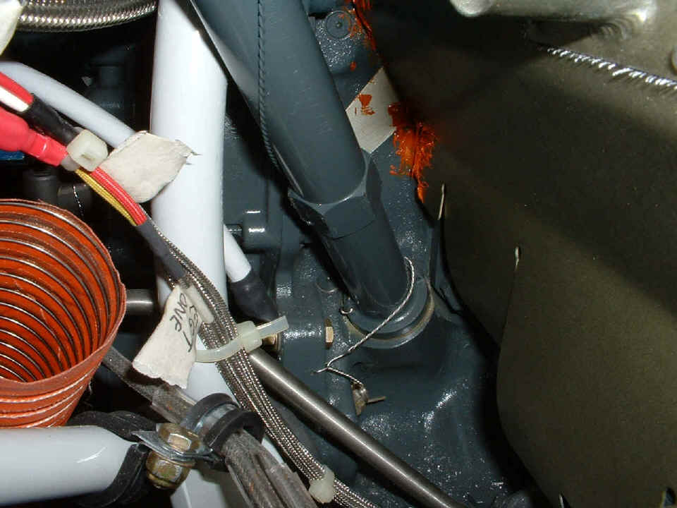
I started sealing up all the cable holes in the firewall. I have seen some excess
RED RTV that got into some places I did not intend to cover. I noticed some of it on
my left forearm, but I don't know how it got there, but it also got to other places as you
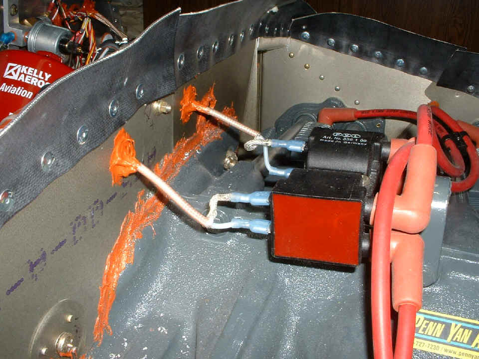
can see on the air seal fabric near the left side of this photo. The photo below
shows the connections of the RG-400 cables to the high-voltage coils of the Plasma III
solid-state ignition. Behind that RED RTV are two 1/4" plastic bushings to
prevent chafing of the cables. The RTV immobilizes the cables to prevent all rubbing
of the cables, even against the plastic bushings. The RTV also seals the air leaks
that would be there if the holes were left open.
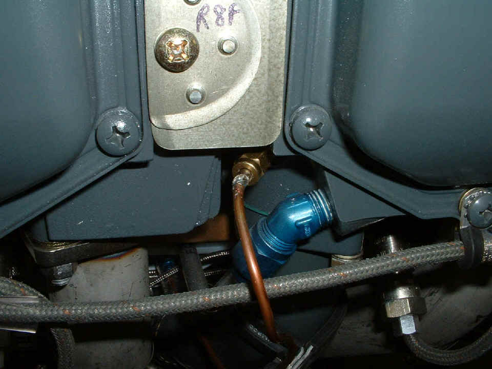
The last photo today shows one of the three brass primer ports which have all
been de-soldered and cleaned of the lead/tin solder and silver/tin solder has replaced it
due to the higher melting point. When I had the AN-800-2 brass fitting off the
copper tubing, I reamed out the solder using a drill bit, and filed off the solder from
the outside of the copper tubing. I then tinned the copper tubing with the silver
solder, and soldered the fitting back in place at the ends of the three copper tubes.
Tests were conducted using a hair dryer to raise the temperature of the CHT and EGT probes on several cylinders to confirm that the wiring is correct to the GRT EIS engine monitor. I also tested the solid-state ignition system using a magnet to excite the two channels on the crank sensor board at the front of the engine. Everything checked out just fine! The only wire left to connect is the P-Lead to the magneto (next session).
| CLICK HERE for Finishing Page 85. | RETURN to MAIN MENU. |