FINISHING - Page 82.
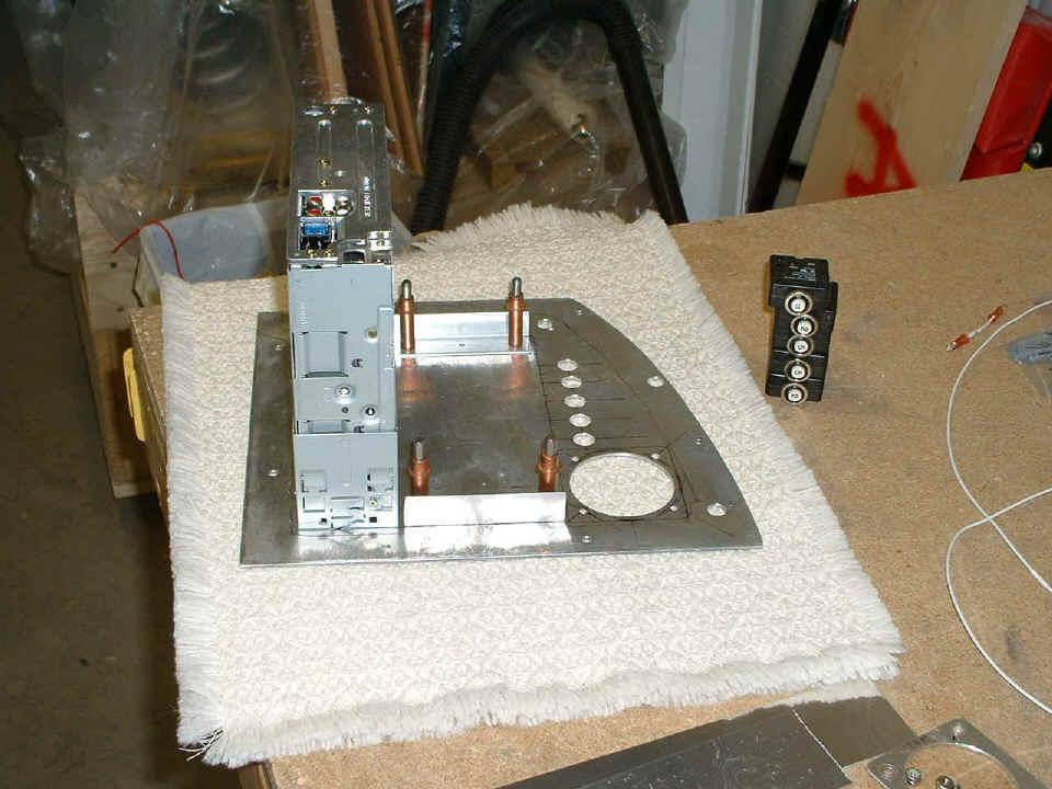
January 5, 2005: Continuing the work this
evening, I drilled the holes for the individual avionics circuit breakers. I put
angles and side plates on the RIGHT panel to mount the CD/Tape player unit securely.
The big round hole is the location of the Hobbs meter. I think there is still
room enough there to put in an XM satellite radio if the mood strikes me.
Here is the finished audio project with a deburring tool under the chassis to
prop the right panel up into something resembling normal position. Both side plates
are riveted to the side of the two angles shown clecoed in position in the above photo.
The bottom of each side plate is riveted to an 0.062" aluminum angle on each
side of the radio chassis, and a brace plate runs across the bottom between the angles.
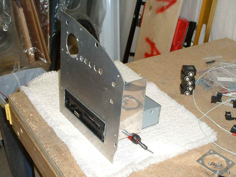
The next time you see this thing, it will be painted pewter gray with everything in its
proper place.
January 6, 2005: The focus this evening was
on the Light Speed Engineering solid-state ignition module. I ran the shielded power
cables to the battery via the pullable circuit breaker that was also moved to the LEFT
switch panel. I called Light Speed to verify something that was confusing about
their optional "P-lead" wiring and where ground connections should be made.
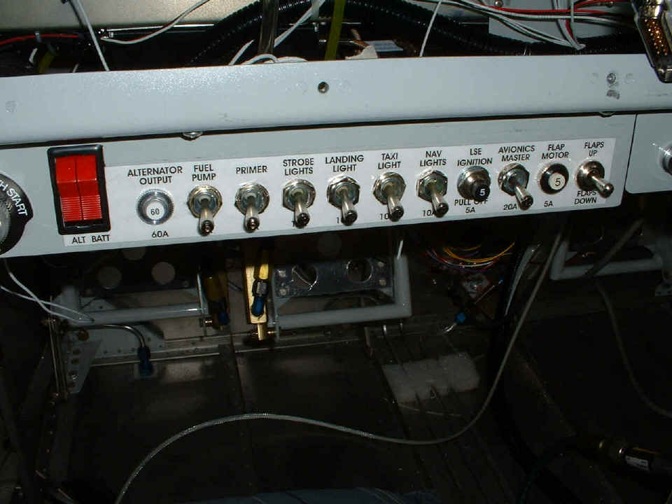
I was assured that the "P-lead" function on their 15-pin D-sub connector
would turn OFF the LSE module when I use the key switch to test the MAG and the
solid-state ignition on engine run-up. You can see I have changed the switch labels
AGAIN. At least this time, I did not have to repaint the switch panel.
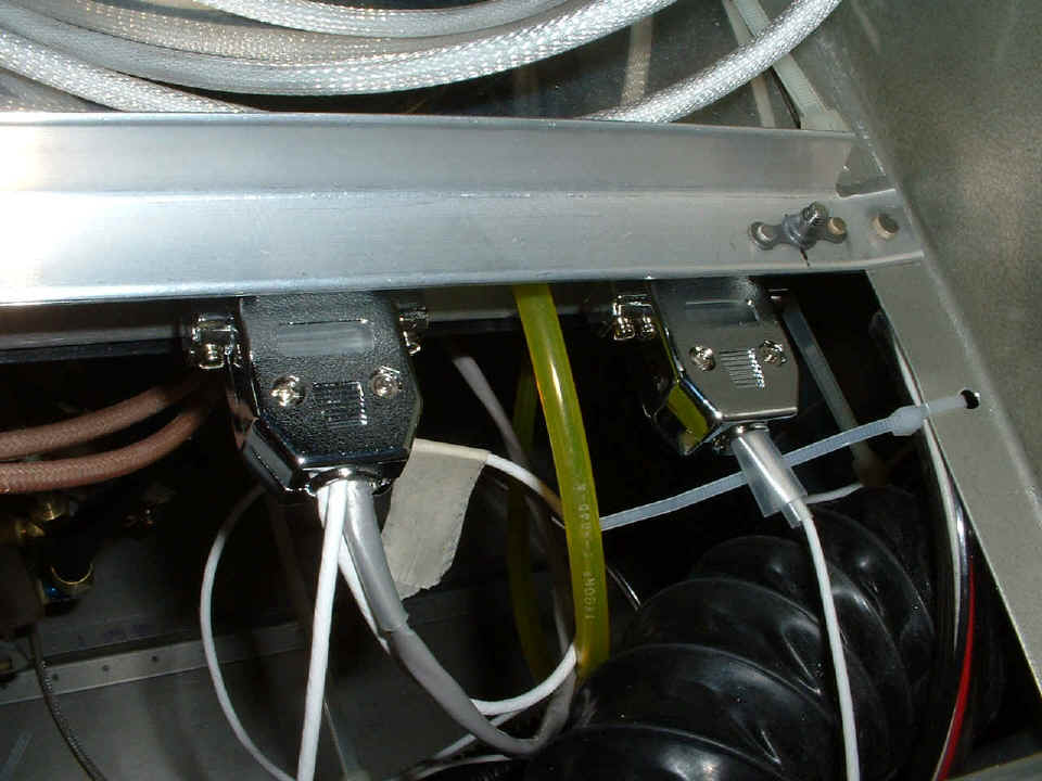
Here is one end of the LSE module with both D-sub connectors visible and the
yellow plastic manifold pressure line connected. The connector on the left has the
shielded white power cables and the gray crank angle sensor cable going into it. The
connector on the right is the one with the "P-Lead" that connects to the starter
switch on the LEFT switch panel. The two beige coax wires come from the other end of
the LSE module and run to the high-voltage coils on top of the engine. I will be
connecting those soon. The LSE module is secured to a mounting plate with screws and
can be removed for service if needed.
While I was working on the starter switch, I put the MAG "P-Lead" on the switch and routed the wire through the firewall to be connected to the magneto in the next work session. You may see some masking tape on wires here and there. Those are my labels reminding me what the wire is and where it is going. The one in the photo above has the writing on the other side.
I also painted the right main instrument panel that I worked on yesterday. It is still drying in the garage and won't get anything put into it for at least another day, probably on Sunday when the paint is good and hard.
The US mail delivered my box from Van's with the replacement GLASS red lens for the Whelen LEFT marker light. The stainless steel pitot tube was also in the box and is much more substantial than the one I had made from soft aluminum tubing per the plans. It came with a RED pitot cover to keep bugs out when tied down or in a hangar -- to be removed before flight of course!
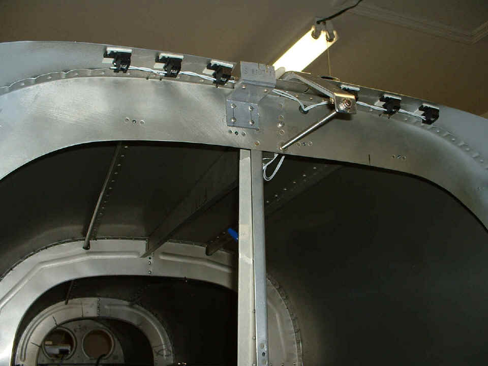
January 7, 2005: I put the LED lights up in
the top of the baggage area. You can see that I have added a 1/4" rubber
grommet in a 3/8" hole I enlarged with my unibit. I put a screw in an existing
hole where the two bulkhead halves are joined to act as a ground point for the negative
leads from the two LED strings. I taped the positive wire down the back side of the
aluminum angle that is part of the F-728 bellcrank channel. I turned off all the
lights in the garage and checked out the available light from the six LED's. It
looks like this is a good idea. I could add more on the bottom of the seat back
bulkhead and may do so as the project progresses. Each string of THREE series-wired
white LED's needs around 65 mA of current from the 12-volt system.
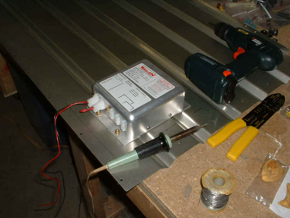
I put the Whelen strobe power supply on the back of the F-651 lower baggage
bulkhead and wired its power plug into the airplane. I took this picture while my
soldering iron was heating up. The black wire is crimped and soldered to the ground
lug that I later secured to the F-728 bellcrank channel at the nut that holds the elevator
bellcrank in place.
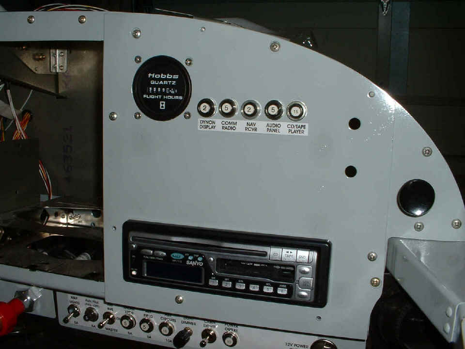
January 8, 2005: This was a Saturday and a
day to work a couple of sessions on the airplane. As I said a few days ago, this
panel would be all dressed up for its next picture. I still see the possibility of a
few more breakers here, but that will be determined later. Once I got this panel
installed, it was time to start the wiring harness using the Molex connectors I bought
recently. In case you may have forgotten, that round black knob at the far right
edge of the photo is the cabin heat door control. I suppose it is time to put a
label there.
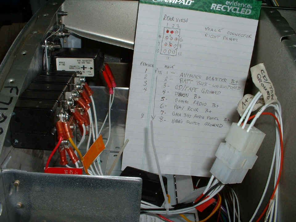
Here is the view behind the panel shown above. I wired the male Molex
connector and harness to the breakers and the CD/Tape player while the panel was on the
bench. I put the panel in the plane and started to wire the connections I could make
today. This pad has more notes on it at the end of the day as I write this to share
with all of you. At the time I had taken this photo, there were only five wires
connected on the airplane side of the wiring harness. When the COM/NAV radio and
audio panel arrive, I will be able to complete the connections.
I powered up the CD/Tape player, but have not hooked up the headphones to the line outputs. The speaker connections will never be used. I also wired up the Hobbs meter. It currently has 9999.9 hours on it, ready to roll over when I get to the airport before the first engine start. Since I could not wire up things that are not on hand, I started to wire up sensors to the Grand Rapids Technologies Engine Information System. Those pictures begin on the next page.
| CLICK HERE for Finishing - Page 83. | RETURN to MAIN MENU. |