FINISHING - Page 81.
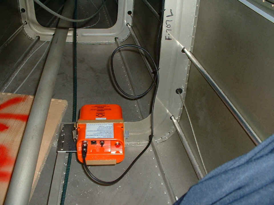
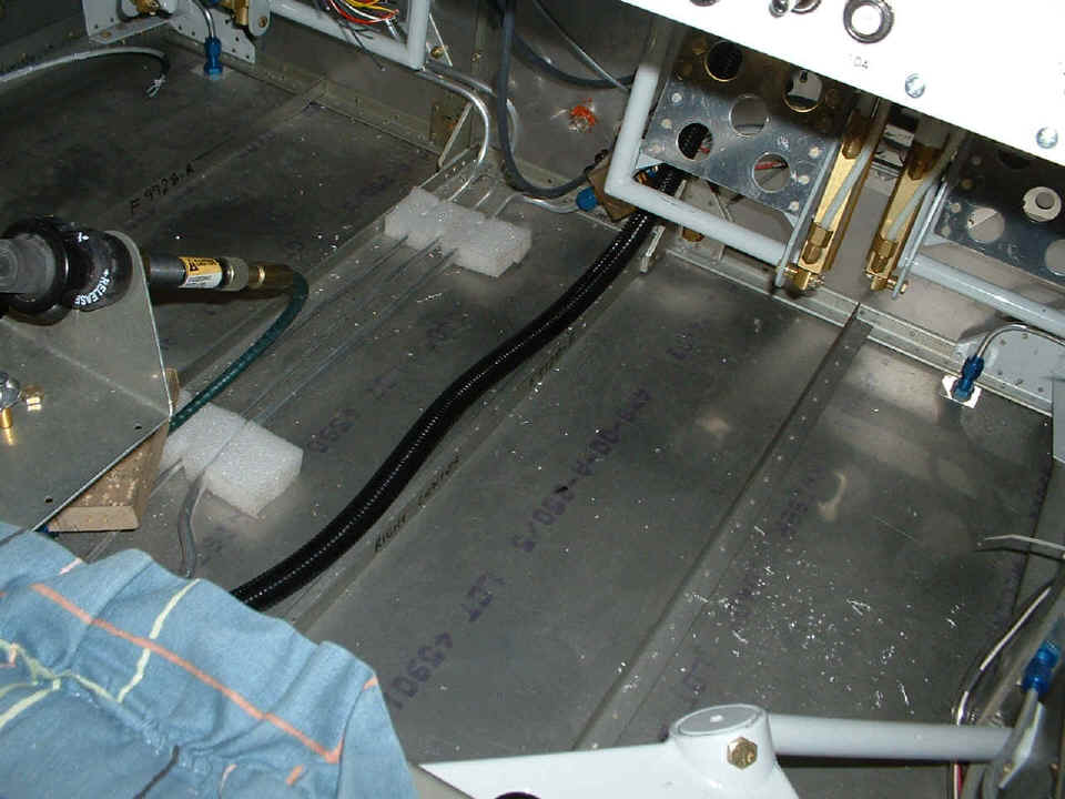
January 1, 2005: I worked 9.3 hours today in three sessions and have a couple of milestones to report. First: The ELT is mounted in a safe place in the tail cone. I fabricated a mounting plate from 0.063" alclad aluminum and riveted it in position to the F-707L bulkhead as you can see from my early notes to myself. There is an aluminum angle riveted to the aft edge of the plate that is also riveted to the bulkhead. I used the existing angle on top of the center rib as the other mounting location for the plate. The ELT antenna coax is secured to the flat edge of the bulkhead at several places. All I have to do is buy some batteries and plug in both ends of the telephone cable to test it, but that comes later at the airport.
That is my pants leg in the lower right corner of the picture. With my six-foot body, I have to go through some minor contortions to get back in there. Except for putting in some protective conduits between bulkheads, I won't have much reason to get in there once the strobe power supply goes in on the back side of the lower baggage wall panel that closes the tail cone at the F-706 bulkhead. Speaking of the strobes, I drilled access holes in the outer corners of the F-705 and F-706 bulkheads and installed plastic bushings to pass the shielded high-voltage wires from the power supply to each of the wings when they are attached. One wire will run under each seat floor between the outer wall seat rib and the first rib going toward the center of the fuselage. I put in the elevator push-rod tube to be sure that it was clear of the ELT when I got it mounted.
I also have some antenna wires to put down there when they come. I have
the coax for the radar transponder, and could install the antenna at any time now.
I also have the COM antenna, but won't install that one or the 75 MHz marker beacon
antenna until the units arrive with the pre-built harness and coax cables from my Van's
order (Pacific Avionics).
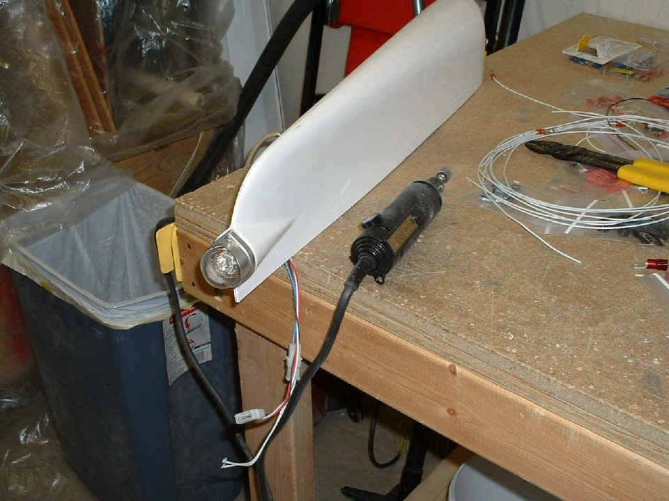
Here is the other picture/milestone for the day,
the holes are drilled to mount the first strobe light at the bottom of the rudder. I
need to run down to Ace Hardware to get a couple of 1-inch long 4x40 screws with Nylok
nuts and flat washers to mount this thing properly. Why would I get 1-inch screws to
go through 0.060" fiberglass? Because it would be very hard to put the flat
washer and nut on a shorter screw in the narrow confined space back in that part of the
fiberglass shell. Right now, the assembly is just plugged into the three holes
drilled into the fiberglass. I used a 1-inch hole saw on my drill, then massaged the
hole to the 1.1-inch diameter of the light fixture using the Dremel sanding drum.
The two mounting screw holes were the only other requirement.
I hope to get the wiring completed to the panel some time in the next few sessions. I have to get a suitable Molex connector to make the connections to the various panel lights. Those lights are from the Grand Rapids Technologies EIS engine monitor, the low oil pressure / Hobbs switch, and the supply voltage to the solid state ignition module. I also need to order a few more low-current circuit breakers for the various avionics items before my wiring can be completed.
January 2, 2005: No airplane work today, I went to see my youngest son in Kennesaw, Georgia for a movie and dinner.
January 3, 2005: I placed an online order with Aircraft Spruce & Specialty for additional circuit breakers for the avionics, and additional 20-gauge Tefzel wire to complete the panel wiring of lights, etc. I was also examining the marker lights to see how many screws are needed for mounting. The wing tip lights must be disassembled to access the mounting screw holes. Unfortunately, the RED lens in the LEFT light is made of glass, not plastic. Yep, it hit the floor and that was that. I ordered a replacement from Van's Aircraft along with a stainless steel pitot tube and RED cover.
The other minor thing today was to discover that a long screw was not the answer to the tail light mounting issue. Plan B will be implemented in the next work session. I also went to an electronics supply house to get Molex connectors for the wing lights and the panel lights and other connections to the instrument panels not already supported by existing wiring harnesses.
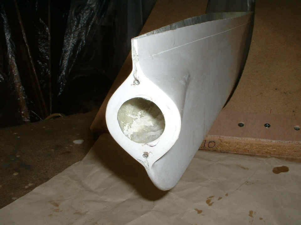
January 4, 2005: Here is plan B, an idea
from David Edgemon. I started to fill the aft end of the rudder cap with epoxy resin
after taping off the "slot area" below the light mount. It only took a few
seconds for the epoxy to run away - down the inside bottom of the fairing. I grabbed
a Kleenex tissue and proceeded to swab the epoxy back toward the aft end and realized I
could make a slurry of the tissue and epoxy to fill the gap and give some place to drill
and tap for the #4 screws that secure the tail light. I may also fill the area with
baking soda and saturate it with cyanoacrylate "super glue" to provide a very
solid mass inside the screw holes for tapping. Both top and bottom screw-hole notch
areas got the treatment.
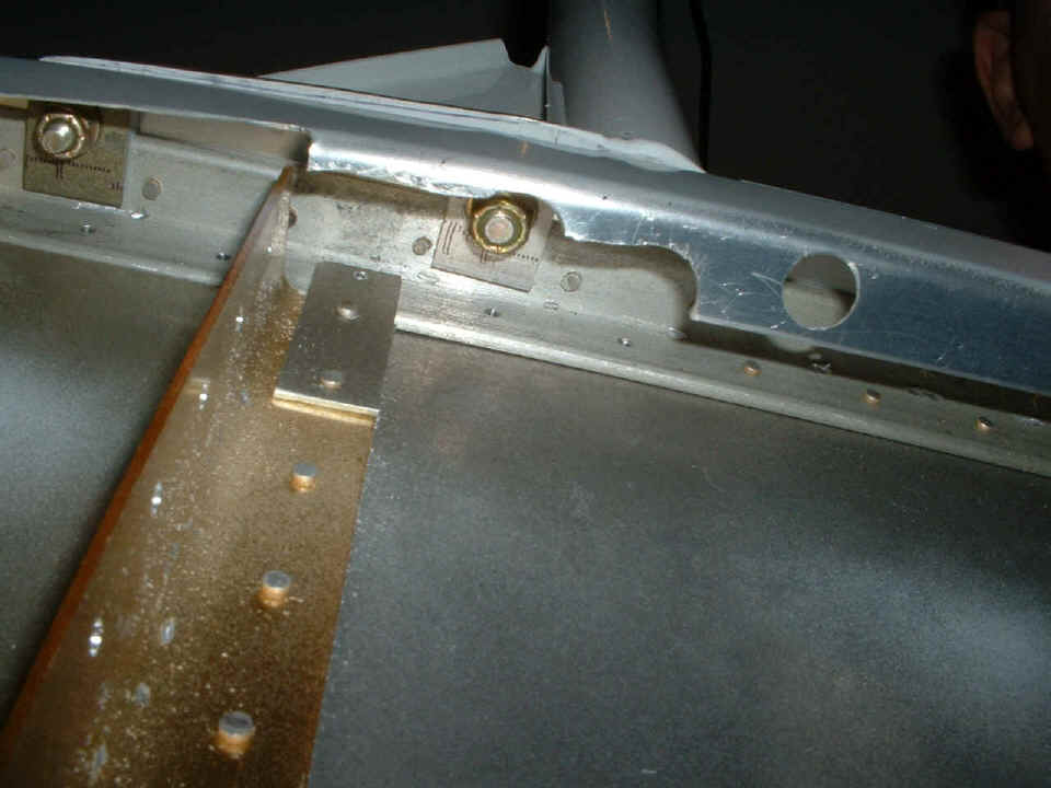
The other thing I took on today was to get the clearance for my bucking bar
when it is time to rivet the top forward skin in place. I took this shot by looking
at the camera view screen in a mirror. The camera is down near the wing spar looking
back up under the right side of the windshield roll bar where it attaches to the longeron
and the aft canopy deck. You can see where I have used my hand nibbling tool to open
up the bottom side of the aft canopy deck past the last open rivet hole. And yes,
that is my right wrist you see in the upper left corner of this picture.
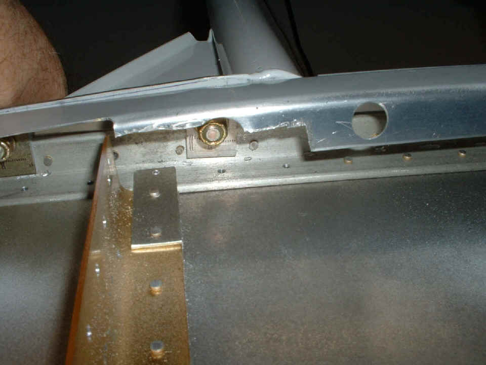
Since I could not leave that ragged cut there, I used my Dremel sanding drum
and a deburring tool to clean up the area. The LEFT side of the fuselage got the
same treatment. The round hole is one of the screw locations where the canopy slide
rail is attached to the aft canopy deck.
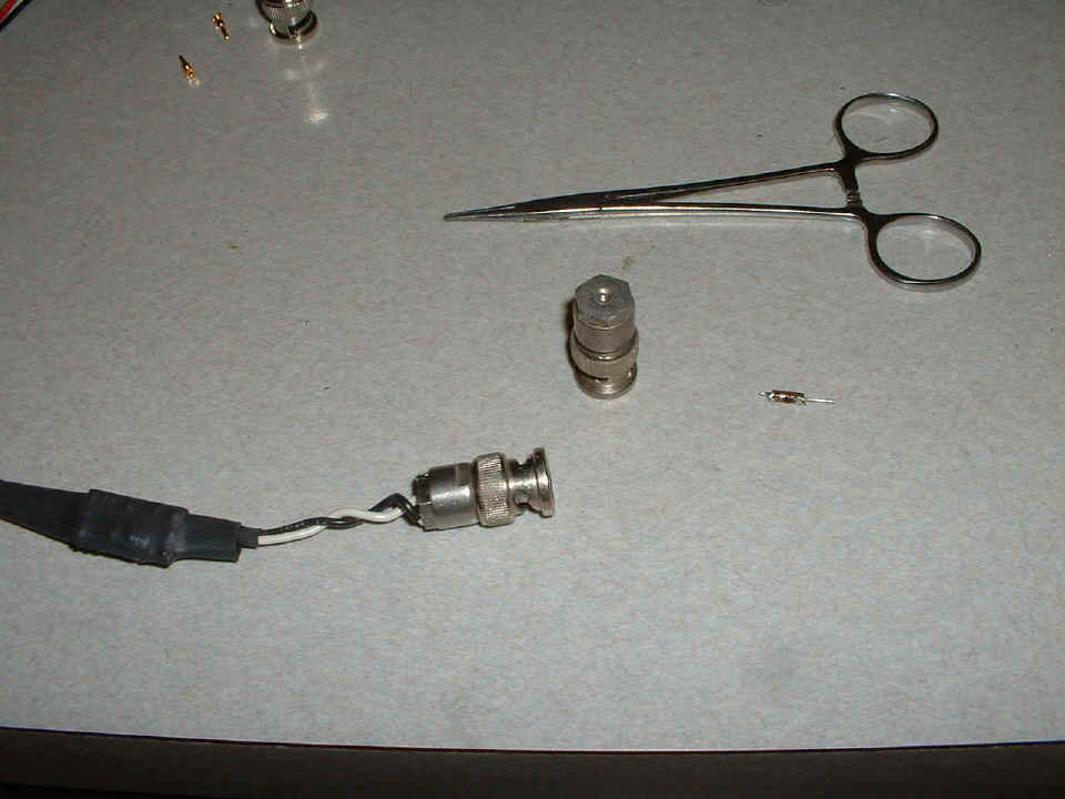
The last picture of the day shows one of the capacitive-to-voltage converters
receiving a BNC connector from my old collection. Van's sells these under the part
number IE P-300C with the BNC connector already installed. There are two of them
without the BNC connector included with the dual fuel gauge when you order part number IE
FL-2C. I had to put on this connector to make the connection to my fuel tank
capacitive probes. The BNC connector originally had a 75-ohm terminating resistor
for video use. I had these two in my satellite video days of the 1980's. One
is still intact, while the 75-ohm resistor I removed from the other is on the kitchen
counter. I have had those 5-inch long hemostats since I was in the US Army in Seoul,
Korea (1969). No, I was not in the medical corp, I got them to work on
electronic
components.
I called Van's Aircraft after receiving an email about my order placed for the lens and stainless steel pitot tube. The order shipped today via priority mail and could be here on Thursday or Friday for sure. My last item back-ordered from Spruce before Christmas is also shipping via priority mail. The log book now stands at 1484.1 hours of aircraft construction time.
January 5, 2005: UPS delivered the order
from Spruce with the wire and circuit breakers early in the work day. I have
actually been taking some calls for the company now that the holidays are over. The
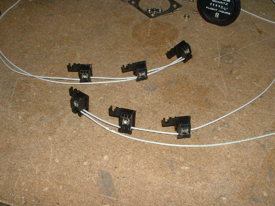
work on the airplane this evening included wiring two sets of three white LED's in series
for baggage area lighting. I tested these on the dimmer circuit and directly across
the 12-volt battery. I have plenty of these left over in case I want to use them
over the instrument panel for lighting. I used scraps of 18-gauge wire left over
from Van's wiring kit since it was the right size to engage the wire clips that are
already in the light fixtures you see below. In the original store-bought
installation, there were FIVE of these white LED's in parallel across a 4.5 VDC power
source. The front set plainly shows the series wiring I have implemented to run on
12 to 14 volts DC directly. Three LED's at 4.5 volts each in series equals 13.5
volts. I made two sets to put on each side of the slider bar underneath the aft top
skin in the baggage area for night lighting.
I cut a slit down one side of the black corrugated conduit from Van's wiring
kit to wrap it around all the wires in the center floor area. There are still more
wires to slip into that conduit. One will be the power wire to the lights in the
baggage area. The other wire is actually a coaxial cable for the VOR/ILS/GS
receiver. That piece of RG-58 coax will not be installed until I get to the airport
and put the tail feathers on this bird. And there it is again, aluminum shavings
from drilling holes for tie-wraps to hold conduits to bulkheads.
That's eight pictures for this page, so lets move on to PAGE 82 and continue with this evening's other adventure -- SOUND!
| CLICK HERE for Finishing Page 82. | RETURN to MAIN MENU |