FINISHING - Page 80.
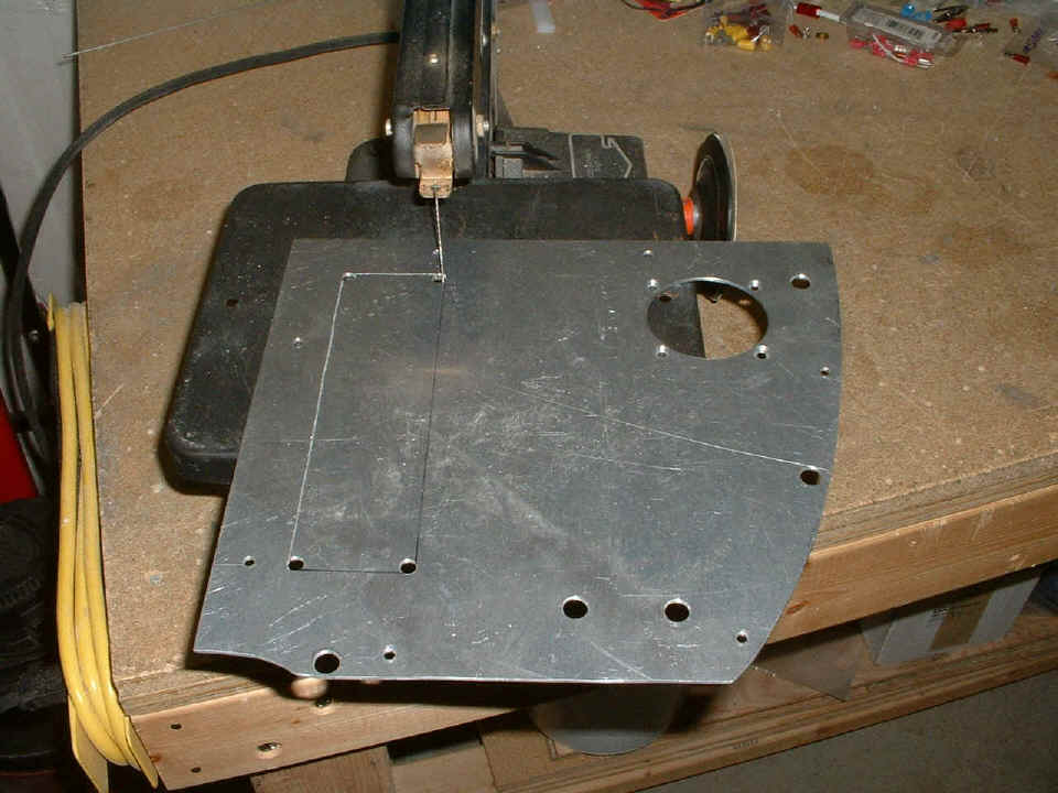
December 27, 2004: I bought a Sanyo combo
CD/Tape player unit today and made the appropriate modification to the right side of the
instrument panel to accept it. Here is my trusty Dremel scroll saw doing the usual
thing.
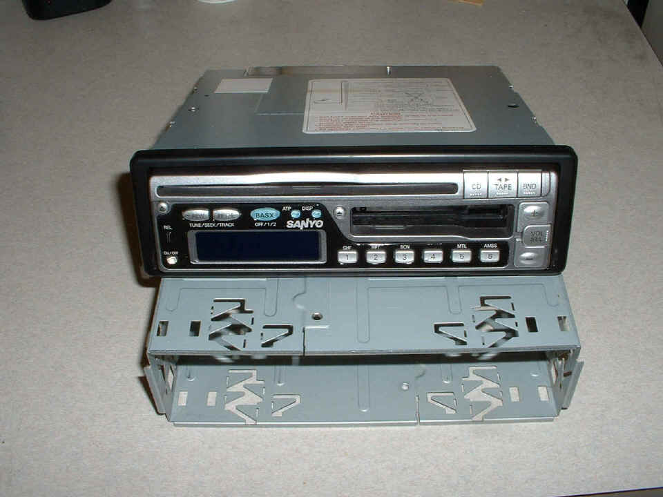
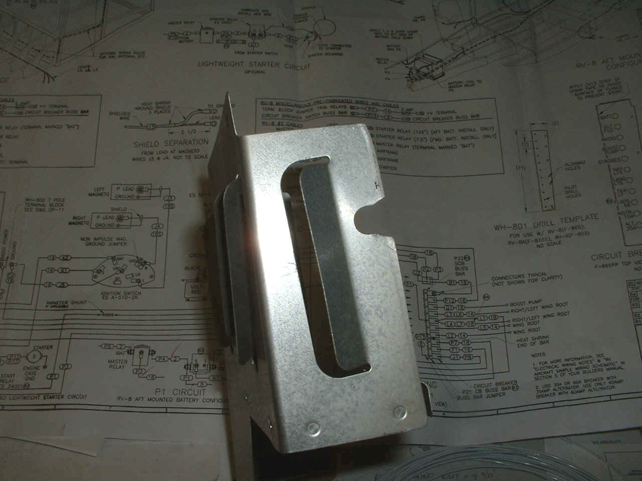
This is the photo of the unit and its mounting frame. It will be a while
before I actually mount it in the panel. There is no need to do that until the audio
panel arrives sometime in January from Pacific Avionics (Van's order).
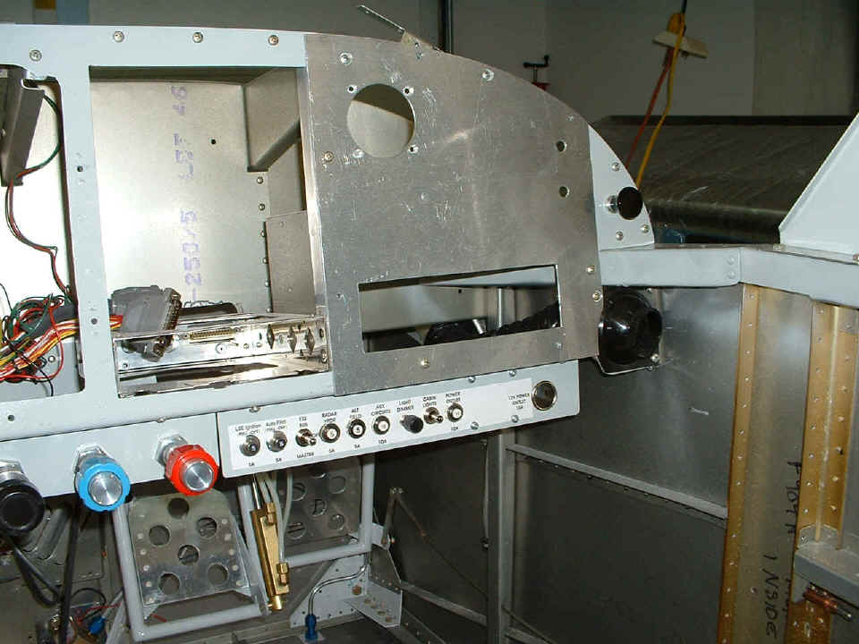
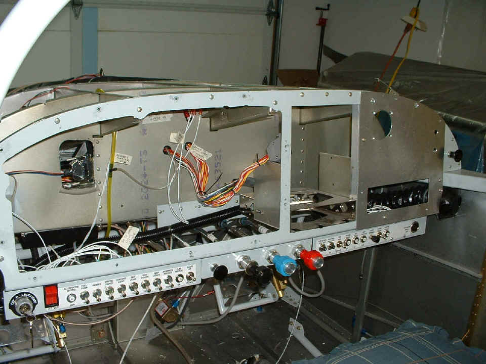
Here is the right panel mounted back in the airplane after much filing and
deburring of the cutout. Behind the panel there is about 1/8" clearance from
the panel frame adjacent to the radio stack, and there is about 1/4" clearance from
the forward canopy deck on the right side.
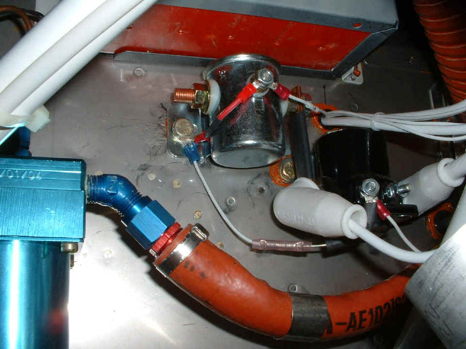
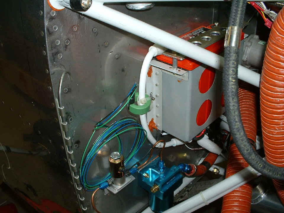
And I also made some minor changes to the firewall side of things. This
photo shows the changing of one of the damper diodes across the master solenoid, and the
change in the ground point for both diodes from the starter solenoid and the master
solenoid. The new ground point is one of the attach bolts to the master solenoid.
The battery cable will be reinstalled when I put in the "keep alive" DC
bus to feed the Dynon, CD/Tape player, and the breakers for the other "must
have" electronics if there should be a failure of the alternator.
December 28, 2004: I spent most of the day doing a computer upgrade, actually gathering the information I needed to make sure the process went smoothly, and it did! I now have an 80 Gig hard drive running in this lap top computer that I use to create this web site and just about everything else I do on the web, email, etc. With any luck, I may put in a couple of hours tonight doing something on the airplane.
December 29, 2004: I did not get to work on the airplane yesterday at all. It seems when I posted that entry above, my computer was messed up, I just did not know it until I took out the second hard drive and it would not boot normally. To make a long story short, if you clone your hard drive so that every byte on the old drive is exactly the same as every byte on the NEW drive, then boot the computer with both drives in the machine, nasty things can happen. I lost no data, but I did finally get the tip I needed to get BOTH drives restored to independent "bootable" condition. Many thanks to Mark Dobson at Apricorn for his tip on using a Windows 98 boot disk and the FDISK /MBR command to straighten out Win 2000 hard disks again! All during the time the two drives were dependent on each other to boot the computer, I could not run this web publishing program, Front Page 98. (All of this was finally resolved late this afternoon, December 30th.)
In between aborted attempts to fix the computer, I managed to do some work on the airplane on the 29th. I built a DC bus bar per the plans, and used it as an essential bus. That means that anything that is attached to it is ALWAYS hot. The avionics switched circuit breaker is connected to it, along with the DC power outlet, and the auxiliary circuit which will power the CD/Tape player. I read the specs on that unit today and realized that IF I were to connect speakers to it and run the volume way up, it could draw as much as 13 amperes! It sure is good to know that the unit will never have any speakers connected to it at all, but have only line out connections to the Garmin audio panel. I will let you know what the current draw is when I play a tape or CD when everything is installed.
I spent much of the 29th threading wires through the black conduits and making connections. Not much to see there, so no pictures to post for the 29th of December. It was a day when I put in 7.7 hours. It seemed much longer due to the difficulty of getting the last wires into the conduit to the primer valve and the electric fuel pump. I checked them both with the battery connected and you can hear them do their thing.
December 30, 2004: Today was a good day to
finish up a lot of wiring. I put the 14 gauge wire into the wings for the landing
lights on both sides, and wired the servo for the Nav-Aid Devices wing leveler.
There are extra white wires from the essential DC power bus, which is hiding above those
colored wires coming through the panel. That black conduit is new today, with two
holes cut in it to allow access/egress for the wires that don't go all the way across from
one switch panel to the other. Everything is wired between the two panels, except of
course the wires leaving switches and breakers going to things not currently in the
airplane.
This photo shows the current sensor green toroid on the main battery cable. The sensor
drives a display on the EIS engine monitor. It will tell me if the battery is being
charged when the engine is running. I will have to run those wires through to the
EIS unit in the next few days along with getting everything else connected to it - fuel
flow, oil pressure, manifold pressure, etc.
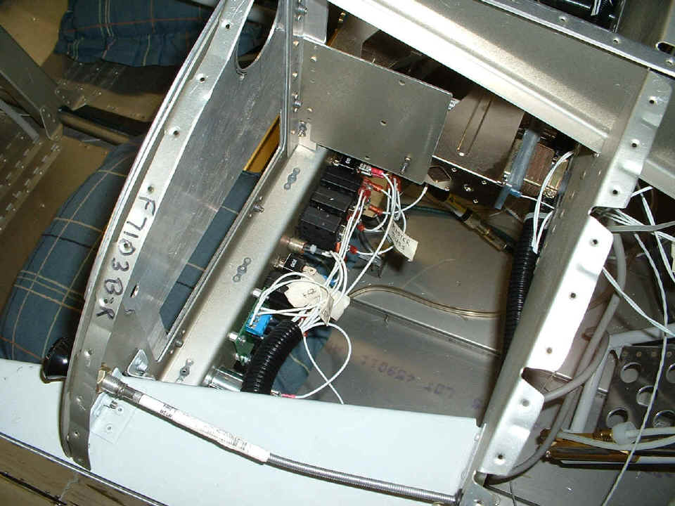
The picture BELOW is the view down behind the entertainment panel before the CD/Tape player is mounted. You can see the panel light dimmer control is connected to the four terminals (BLUE plastic) on the little circuit board near the end of the black conduit. The dimmer power comes from the NAV lights switched circuit breaker on the LEFT switch panel.
I tested the alternator field current circuit with my voltmeter and all is well with that link. The Cessna power switch is interlocked with the 5-amp circuit breaker that is on this panel. The radar transponder, the Light Speed Engineering (LSE) electronic ignition, and the autopilot are all switchable to the MASTER or the ESSENTIAL BUS for power. The GREEN LED on the instrument panel will show power to the LSE module until I get everything turned off at the end of any flight. The NAV/COM, Dynon unit, EIS engine monitor, fuel gauge, and audio panel will be wired via the 20-ampere avionics master switch/breaker to the ESSENTIAL BUS only (battery).
The ground cable going from the transponder chassis is connected to a bolt on
the firewall near the main battery ground cable. I also ran the ground from the 12V
accessory power outlet to that same ground point. (The accessory outlet has a 10 amp
circuit breaker feeding it to run my computer, etc.) There is a second bolt near
that location on the firewall, and it will probably be the ground point for the CD/Tape
player also.
The last picture for the day below is a shot of the notch I had to cut in the
side of the F982C center cabin cover to allow clearance for the cabin heat control cable.
I had to pull this thing out to allow me to run some additional wires into the
center area. I began running the telephone wire that remotely controls the ELT from
the instrument panel. I also had to remove the Dynon remote magnetic sensor serial
cable from the aft fuselage to make way for this phone line. The jack plug needed
the space to get through the plastic bushings in the bulkheads. Tomorrow I get to
put the serial cable back in place and wire it up again. I had been told that I
would put this airplane together TWO or THREE times before it is finished. Today was proof of that ONE MORE TIME!
Add another 5.0 hours to the log book bringing the total to 1471.9 hours. I need to order more wire from Aircraft Spruce & Specialty to finish running the 18 gauge wire to the nav lights in the wings. I used up all the 14 gauge wire for the landing lights, but that is all I need (I think). I have plenty of 16 gauge left, but not much of the 20 gauge. I used most of the 20 gauge on the wing servo control wire, and some on the wire from the dimmer circuit to the eyeball panel lights that have yet to be mounted.
| CLICK HERE for Finishing Page 81. | RETURN to MAIN MENU |