FINISHING - Page 79.
December 26, 2004: I started on the punch
list with two more highly visible items. I made a mounting bracket for the VOR/glide
slope antenna and mounted it to the top of the vertical stabilizer. Here are the
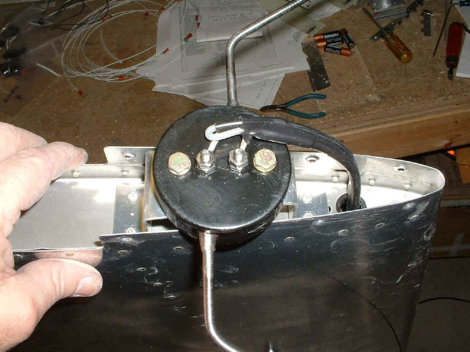
details of the mounting bracket I made from some 0.063" aluminum plate. This
photo shows the last bend being put in place. I drilled all the holes and marked the
bend points when it was still a flat sheet.
The "hockey puck" that holds the dipoles is mounted with a pair of
3/16" AN bolts to platenuts riveted to the bracket. The two screws facing
"up" are the antenna connections to the dipoles. The AFT end of the
bracket is to the right in this photo.
I drilled out the two hard rivets in the top of the vertical stabilizer (VS)
and used the existing holes in the VS center spar and the top rib as the AFT attach point
for the bracket. The two rivets at the front are in the top rib only. This
macro shot shows the clearance of the bracket inside the fiberglass cap that goes on top
of the VS. I used Cherry Max pop-rivets to hold the bracket to the VS when the
clecoes were removed.
Now that the antenna is bolted on to the bracket, the coax cable has to be run
through the forward section of the vertical stabilizer. An old unused rod from a
hinge makes a perfect fishing tool to pull the RG-58 cable through two plastic bushings
installed in the top and bottom ribs. The leading edge of the VS has no center rib
on the front side of the VS spar. There is a center rib on the AFT side of the main
VS spar, but that is not an issue here. The rivets clearly show the locations of the
various internal parts. Notice the hemostat holding the hinge rod in place until I
can tape the coax on the other end. You can also see how I was a bit heavy-handed
with the rivet gun on the VS spar. What can I say, that was two years ago and my
skills have improved a bit doing the wings and the fuselage (blah-blah-blah).
Next comes the connections to the BALUN portion of the coax assembly.
Notice that the cable connections are at right angles to the two AN mounting bolts so as
NOT to short out the VOR/LOC/GS signals. You can also see that the hockey puck is
wider than the top of the VS skins. I could just barely get the unibit in there deep
enough to open up the 5/8" hole to mount that plastic bushing. And yes, there
are two RG-58 cables heat-shrinked together to form the BALUN. That is the reason
for the large plastic bushing here, and only a 1/4" bushing on the bottom rib.
I had fiberglass dust flying again from my Dremel sanding drum. I also
used my metal snips on the glass to keep the dust to a minimum. Here you see the end
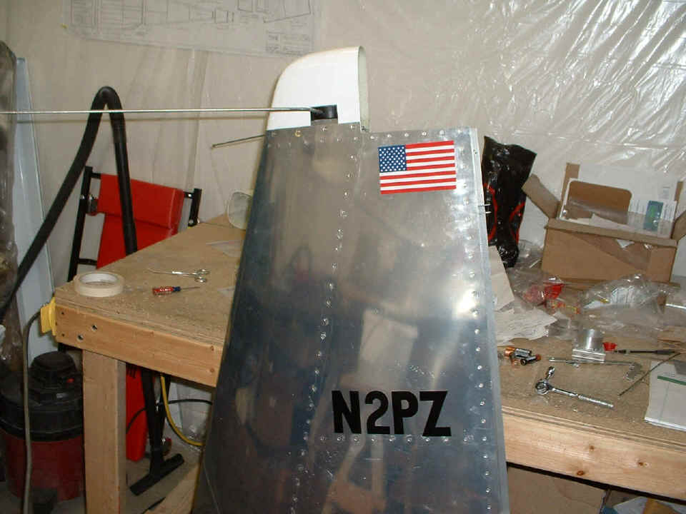
result of my morning/early afternoon work session. I also made a pair of aluminum
plates to fill the 1/4" air gap since my bracket turned out to be a little too
tall. I used #6 platenuts and 6-32 flat head screws to hold the fiberglass cover and
the gap filler plates in place. The flag sticker came in the mail as a promo, so it
ended up on the VS. The N2PZ numbers are from Home Depot and meet the minimum 3-inch
size required by FAA regulations. They are temporary until the airplane goes into
the paint shop, probably after I get 20 or 30 hours flight time. I want to have the
paint scheme done before the 40 test hours are completed and flown.
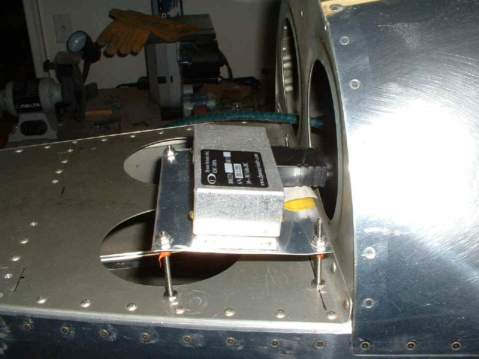
And the last shots of the day are after my evening session showing the results
of the wiring and mounting bracket for the Dynon remote compass sensor. The aluminum
scrap pile is getting smaller. I stopped work for a mid-afternoon meal, then went to
Lowe's to get some stainless steel, non-ferrous screws to adjust the mounting plate below
to the same 8-degree down angle as the Dynon display unit in the instrument panel.
There are lock washers under the aft deck plate and above it also, to firmly lock the
screws in place. I used 2-inch screws, then doped the second set of nuts that
hold the plate up off the deck. There are lock washers under the mounting plate on
top of the second nuts, and some of that RED silicone RTV to also "lock" the
plain nuts in place. I used Nylok nuts on top of the mounting plate. The
EDC-10A is mounted to the plate using #4 round-head solid rivets. The upper nuts
adjust the mounting plate to a level condition in the LEFT/RIGHT plane, and down 8 degrees
in the longitudinal plane.
Before I could put this assembly together, I pulled down the horizontal
stabilizer and mounted it loosely to the aft deck. That verified where I could NOT
mount the magnetic sensor. I put the fiberglass empennage fairing in place to verify
the lateral limits for mounting the sensor. I also drilled and mounted the Outside
Air Temperature probe, which is wired into the DB-9 serial cable connector in the photo
above. This is the same way David Edgemon mounted his temperature sensor on one of
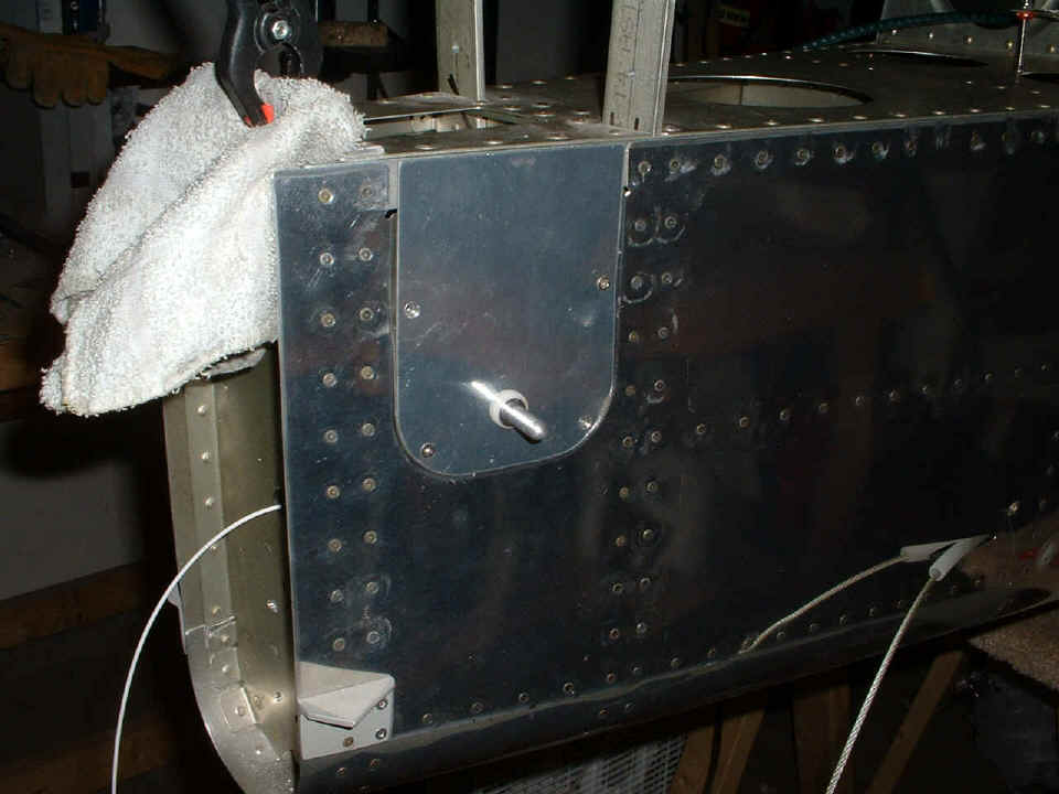
the elevator control arm access plates. I had to add in a pair of small 1/4"
plastic bushings to keep the sensor wires away from the path of the elevator push rod and
the strobe cable that will be down in the bottom of the fuselage when I get it in there.
That white wire at the left of the photo below is the 12-volt power wire that will
go to the white light in the rudder. The shielded high-voltage strobe wire will come
out that same hole, since the strobe tube is inside the Whelen tail light assembly.
And with that photo, this page is complete and a long day is over. Add another 8.6 hours of actual airplane work time today in two sessions. Today's milestones were the mounting of the VOR/LOC/GS dipole antenna to the vertical stabilizer, AND getting the Dynon remote compass sensor with temperature probe mounted, operational, and calibrated! Tomorrow should be a good day to put in the Whelen power supply for the strobe lights, and possibly the ELT in the tail cone crawl space. The airplane construction time now stands at 1456.5 hours.
| CLICK HERE for Finishing page 80. | RETURN to MAIN MENU |