FIREWALL FORWARD - Page 74.
December 5, 2004: Sunday saw 5.7 hours on
rework and some new work. Let me explain it to you. First the good rework.
I had removed the camloc fastener that needed to be realigned with the air
flow on the oil access door. I had filled the two abandoned rivet holes with epoxy
when I was working on the upper cowl on page 72. Today, I used my Dremel sanding
drum to take off some excess fiberglass to get the camloc connector to sit flat with the
outer surface and then riveted it in place.
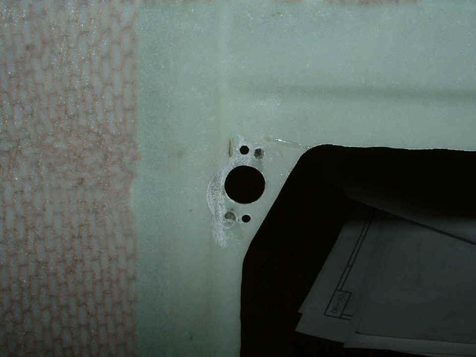
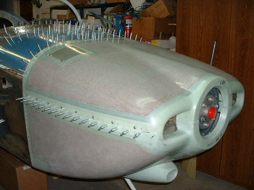
Here is how that connector looks from outside the cowl. With the door
closed and locked, both tabs are "knife-edged" into the air flow.
I then took the upper cowl and placed it on top of the engine and lower cowl and began cutting away the front top sides of the baffles to clear the air ducts that were installed with epoxy on page 72. That went well, slowly, but well. I was cutting off strips of aluminum baffle in 1/4" increments here and there until the upper cowl fit nicely on top of the lower cowl. Then when I tried to put the stainless steel rods into the side hinges of the cowl to lock the upper and lower sections together, the day got ugly.
I thought about some of the other RV's that I have seen using screws to hold the cowl in place and now I know WHY! So after struggling with the rods and hinges to no avail, I started plan B -- platenuts and #8 screws to hold the upper cowl in place. Fortunately, I had not put any epoxy or rivets into the lower cowl hinge locations. I grabbed some 0.032" aluminum sheet and cut some 1.25" wide strips the same length as the hinges on the LEFT side, and due to a lack of appropriate surplus material, I cut the RIGHT side a bit shorter and ended up joining two pieces end-to-end to do that. But it should be OK. I then drilled and clecoed the strips to the lower cowl using the 1-inch-spaced rivet holes previously put there for the lower half of the hinge.
I took the upper cowl to the work table and drilled out all the hinge rivets and separated the hinges from the epoxy that had been put there during the riveting process. I used a single-edged razor blade paint scraper and removed the thin layer of epoxy from the upper cowl where the hinges were previously installed.
After finishing both sides of the upper cowl hinge removal, I placed the cowl
in position on the fuselage and lower cowl, then drilled one hole near the front RIGHT
side through the upper cowl and the upper portion of the newly-installed aluminum strip.
I had left 3/4" of the strip above the seam of the lower cowl to provide
adequate room for platenuts. After fitting the cowl along the RIGHT side fore and
aft to allow the 1/16" gap for paint clearance, I drilled every other hole rivet hole
with a #40 drill and clecoed them as I drilled. Then I drilled every other one of
these new holes from #40 up to the size needed for the #8 screws. I figured I would
put in half of the #8 platenuts before drilling the other half of the #8 clearance holes
to insure accurate placement of all the holes. And that was where I stopped for the
night. When this part of the project is completed, there will be 14 stainless steel
#8 screws spaced two inches apart on each side of the cowl holding the upper and lower
sections together.
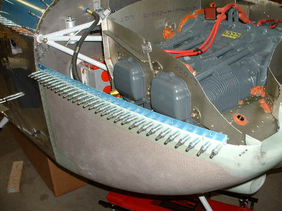
Here is the view of the LEFT side showing how much of the air baffle has been
cut away to clear the upper air ducts now epoxied to the upper cowl near the air inlets.
You can see one #40 hole in the front upper part of the aluminum strip where I held
the LEFT side of the cowl in position while I was drilling #8 clearance holes in the RIGHT
side of the upper cowl. When I have finished the work on the cowl screws, I will
install the black air seal fabric on the baffles to seal the air plenum for optimum engine
cooling. That will be a milestone day since it means the end of cowl work.
December 6, 2004: I spoke with Scott Risan at Van's this evening and he recommended that I use 0.040" thick aluminum strips for the cowl screw mount modifications. With that information in hand, I stopped work on the 0.032" stock and ordered what I needed from Van's along with additional stainless steel screws and platenuts. I also ordered the stainless steel data plate that will identify the airplane, and a pedestal mount magnetic compass. With all the high-tech stuff in this airplane, if any of that fails, there will always be that compass to fall back on for dead reckoning, etc. Speaking of the high tech stuff, the strobe light shipment from Van's is now in Tennessee and approaching my place via UPS. The Dynon unit actually left Redmond, Washington this evening UPS ground and is expected to be here December 13th.
Before my call to Van's, I had put most of the platenuts on the aluminum strip on the RIGHT side of the cowl, but have halted that and went back to verifying the needed clearance of the engine baffles from the upper cowl in preparations for the air seal fabric installation. The aft baffles needed a little trimming but now all is fine.
December 7, 2004: The shipment from Van's
Aircraft arrived today containing the Whelen marker and strobe light
kit. It also had a pair of interior "eyeball" lights, and the small
AN fittings I needed to complete the primer line connections to the cylinders. I put
in only one hour tonight to remove the cowl and the aluminum strips that I had been
working on. I recovered all the steel platenuts from the one strip that
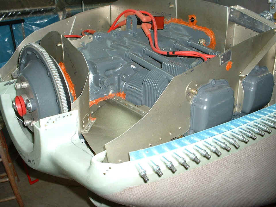
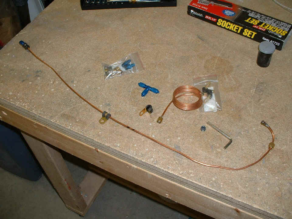
already had them attached. I then took off the crossover copper tube to cylinder
number 2 primer port after marking where I would cut it in order to install the
"T-fitting" as shown in the photo below. I have already installed the
brass primer spray nozzle into the intake manifold port on cylinder number 4. I will
cut the copper tube between those two black marks, put on the AN flare fittings, and
secure the tubing with the extra clamp shown below. When this task is completed, all
three available cylinders will have primer fittings installed. The intake manifold
port on cylinder #3 is used to sample manifold pressure to the electronic ignition system
and the engine monitor for power settings.
The official log book aircraft construction time stands at 1402.5 hours and counting.
December 8, 2004: The last primer port was installed on cylinder #4. The materials you see in the photo above are now mounted in their proper places on the engine. No pictures of that today, but there will be when I get the next shipment of clamps from Aircraft Spruce & Specialty.
December 10, 2004: The shipment of Adel clamps came from Aircraft Spruce & Specialty along with one quart of aviation 100W oil to use on the O-rings of the propeller and fuel lines as needed. I will end up pouring the rest of it into the engine when the time comes. The Dynon shipment left Chicago on a UPS truck and made it to Nashville, TN by late in the evening and came into Chattanooga early Saturday morning.
December 12, 2004: The clamps arrived on
Friday the 10th, but I did not work on the airplane that evening or on Saturday. The
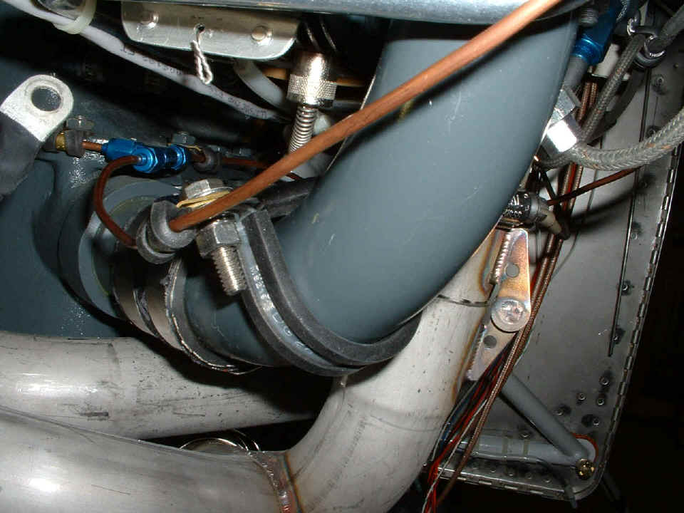
first thing done this Sunday morning was to put the clamps in place to hold the primer
lines steady. The large clamp is 1.75" diameter to fit the intake manifold
pipes. The small clamp is 1/8" around the copper tubing. Look carefully
and you will see another 1/8" clamp to the left of the BLUE AN "T" fitting,
and a second one to the right of it on the line going to cylinder #4. This is the
primer line going to cylinder #2 in the foreground of the picture below.
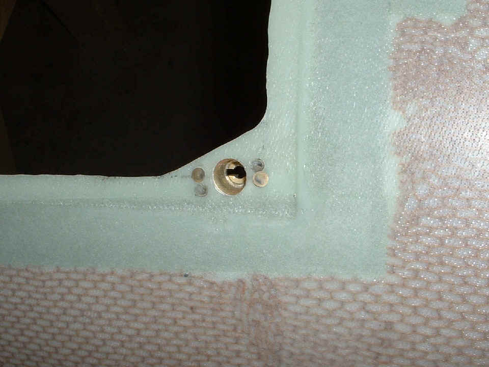
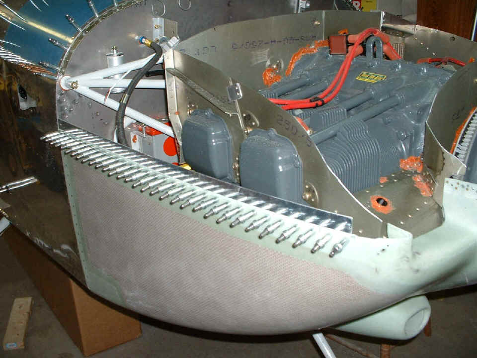
The next shot shows the new 0.040" aluminum plates I received from Van's
to mount platenuts and secure the upper and lower cowl sections to each other. This
photo is before drilling and installing any of the platenuts. Notice the curved
hinges at the top left of the photo on the firewall.
It was my intent to replace the curved hinges with aluminum strips and
platenuts, not just where the sides of the cowling come together, but also at the top rear
of the upper cowl where it meets the firewall. In this photo, all the aluminum
strips now have platenuts riveted in place.
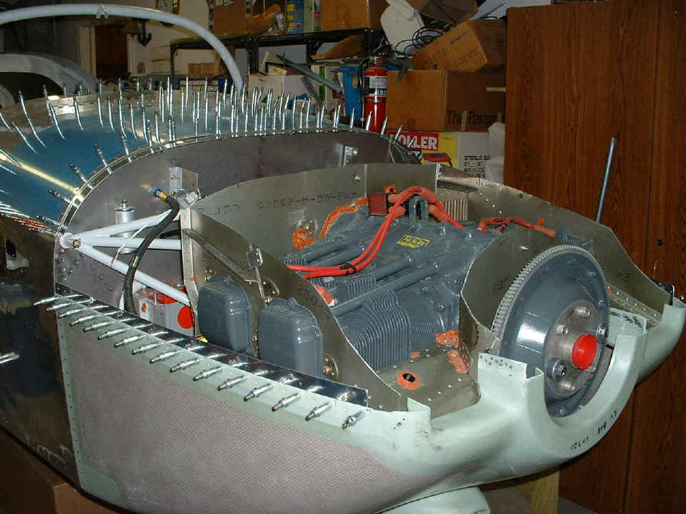
The last picture for this page and for the day shows the cowl held in place by
screws. There are eight screws along the seam to attach the upper cowl to the lower
cowl. I have yet to rivet the aluminum strips in place on the lower cowl.
There are 12 screws across the top rear of the upper cowl to attach it to the firewall.
I will fill any unused rivet holes with epoxy in the next work session.
I worked a split session on the airplane today. I went to Dallas Bay Skypark (1A0) just after 1 PM to check out hangar space that could be available. There is a real possibility that I can get in there very soon. The other bit of news is about my Dynon D-10A unit being delivered by UPS on Monday, December 13. I will provide pictures of course when Christmas comes early!
| CLICK HERE for Firewall Forward Page 75. | RETURN to MAIN MENU |