FIREWALL FORWARD - Page 73.
December 4, 2004: Saturday continued -- I wanted to keep the number of photos on page 72 at eight to prevent slow loading for dial-up internet users who frequent this site from some international locations. HI Luis!
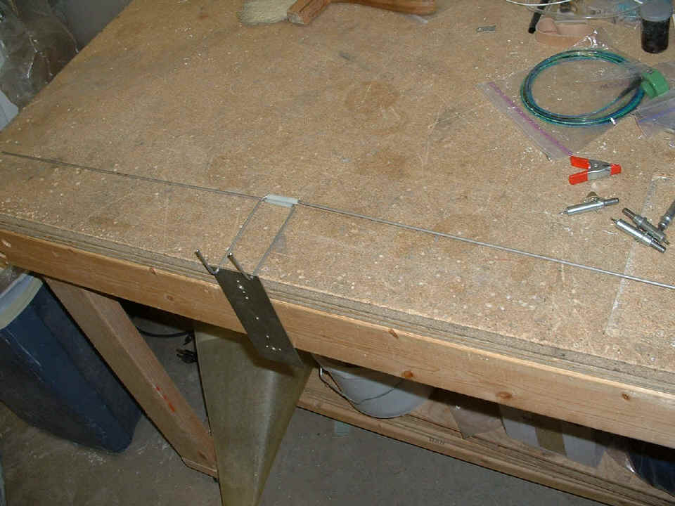
Back to the business of airplane construction with this photo of the stainless
steel rods for holding the bottom of the cowl to the fuselage at the firewall. Move
on down the page to see how these fit into the lower cowl.
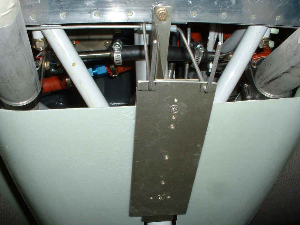
This is how they fit on the underside of the cowl. This is looking up
between the exhaust pipes and behind the nose gear leg. The short pieces of white
nylon brake line tubing are used for anti-chafe protection of the stainless steel rods as
they cross the U-720 brace assembly. I will probably add a doubler plate to the
bottom plate to reinforce the two holes where the rods pass through. By the way, all
the hot air from the engine comes out this open area between and around the exhaust pipes.
Remember, this is an air-cooled engine for those of you who may not be airplane
"savvy."
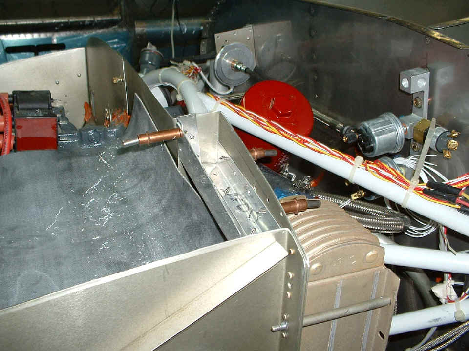
Going topside again, I saw this addition to the
baffle assembly above the oil cooler over at David Edgemon's hangar last Saturday
during my visit to learn about these kinds of details. I wanted to build my own
version and here it is. In this photo it is still being fitted to the available
space. I have made two of the three braces it will need to be secured properly.
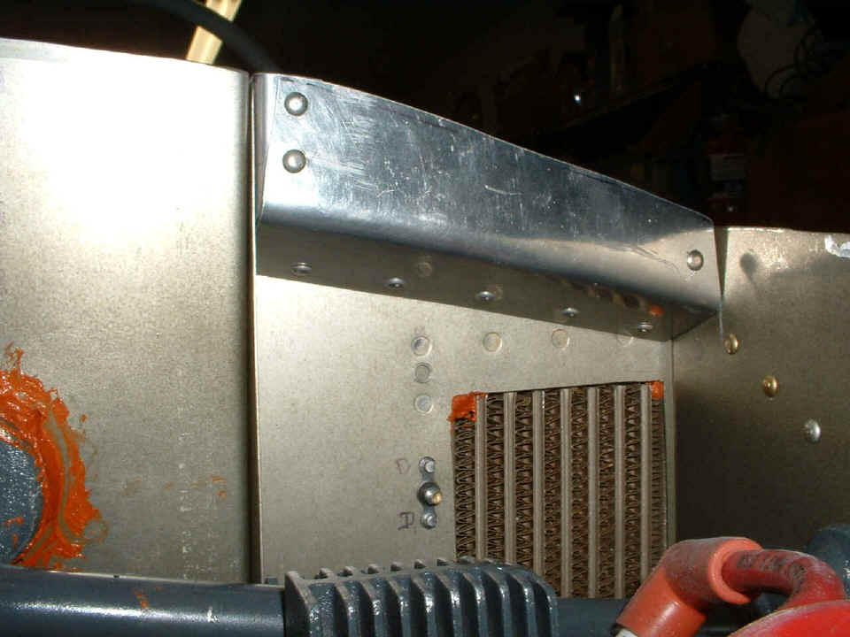
This photo shows all the pieces on the bench before riveting them together.
The smallest right angle brace is the only one NOT riveted together before the
assembly is installed with the remaining baffle components for cylinder number four.
The long angle on the right was bent in a vice using a 1/4" drill bit on top
of the vice. That allowed me to exceed 90 degrees on the bend and did not risk
fracturing the aluminum since the bend is around the radius of the drill bit.
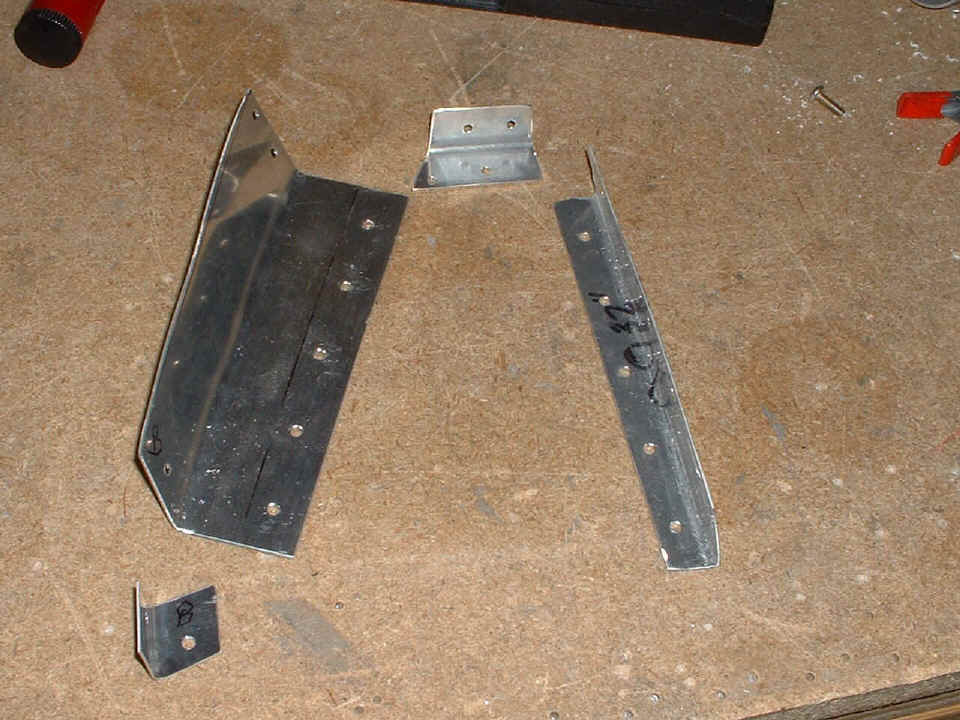
I used LPS4-3 pop-rivets on the back side since I could not get my rivet
squeezer in between the firewall and the back side of the baffle. All the other
rivets are AN470AD4-4 except for the two that hold the angle to the overlap of the
part labeled 6-320 and the part you see that has the pop rivets in it. Those two
rivets are AN470AD4-5. The smallest angle brace with the letter B on it was riveted
in place after installing the assembly in its final position. I took out the rivet
to "nowhere" above the oil cooler since it was in the way and I was going to
cover it with the assembly. Those five extra rivet holes are no longer an issue
since there won't be any airflow in that space when the air seal fabric is installed across
the front of the new baffle assembly now installed there.
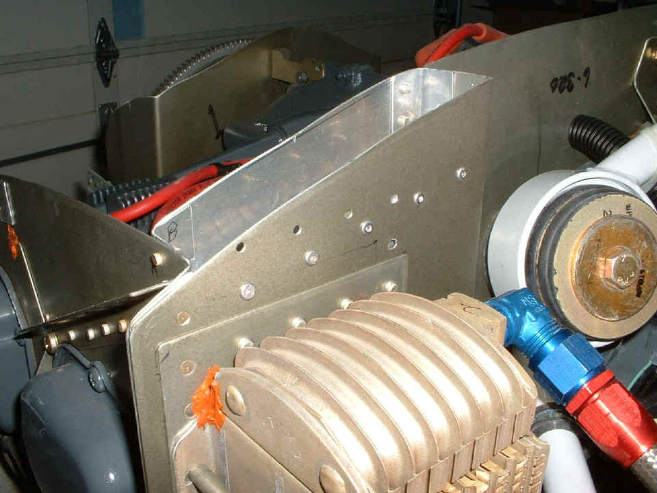
Here is the view of the assembly from the front side showing the slope of the
lower side of the largest piece to encourage easy airflow down behind cylinder number four
and also into the oil cooler. The angles fill the gaps at the ends of the large
piece. Due to the way this piece is angled, starting with a rectangular aluminum
plate that is already cut to the distance between the outside baffle and the 6-320 piece
at the left of this photo is NOT the way to begin. If you try this at home, build a
cardboard template first. Since I was working with scrap, I was not so worried about
it. Besides, most of this is going to be hidden by the black
air seal fabric anyway.
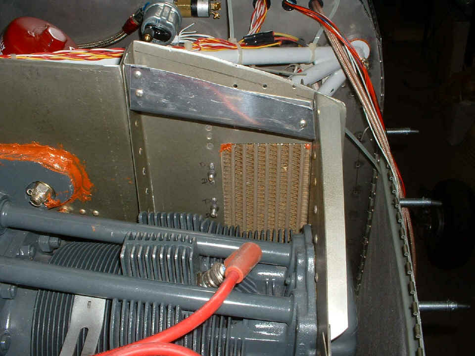
Here is a second view from a higher perspective showing more detail of the top
side of the assembly. All the parts came from my scrap pile and are made from
0.032" and 0.035" Alclad aluminum sheets. I did not use any extruded angle
stock since none of the angles wanted to be exactly right angles of 90 degrees.
I just reviewed the first pages of my construction log book. The first entry is on September 27, 2002 when I ordered the preview plans from Van's Aircraft. The book was shipped on September 30th and delivered on October 7th. My first visit to David Edgemon was on October 12, 2002. My first preparations of the garage began on October 15, 2002. I began the log book on October 16 and entered all the above information in this paragraph. That was the same day I started my Excel spread sheet log book that tracks my costs and work hours. The first five pages of the log book documents prep work and ordering tools from Cleaveland plus some local purchases. I can see that I have to develop that old roll of film in my 35mm camera and get those photos added to the front of the web site. The first digital camera pictures show up on the web pages on November 29th on page 2. I can see that some of the beginners will wonder if I really built the empennage since my coverage of it scarce.
That completes the review of Saturday's work session. I will have more for you tomorrow night. The total work time on the airplane stands at 1393.3 hours since October 28, 2002.
| CLICK HERE for Firewall Forward page 74. | RETURN to MAIN MENU |