FIREWALL FORWARD - Page 72.
December 2, 2004: Four hours tonight working
with some new parts I received from Van's Aircraft today. As you can see the cowl and the
forward top skin are OFF again. I thought I would start with some thing easy -
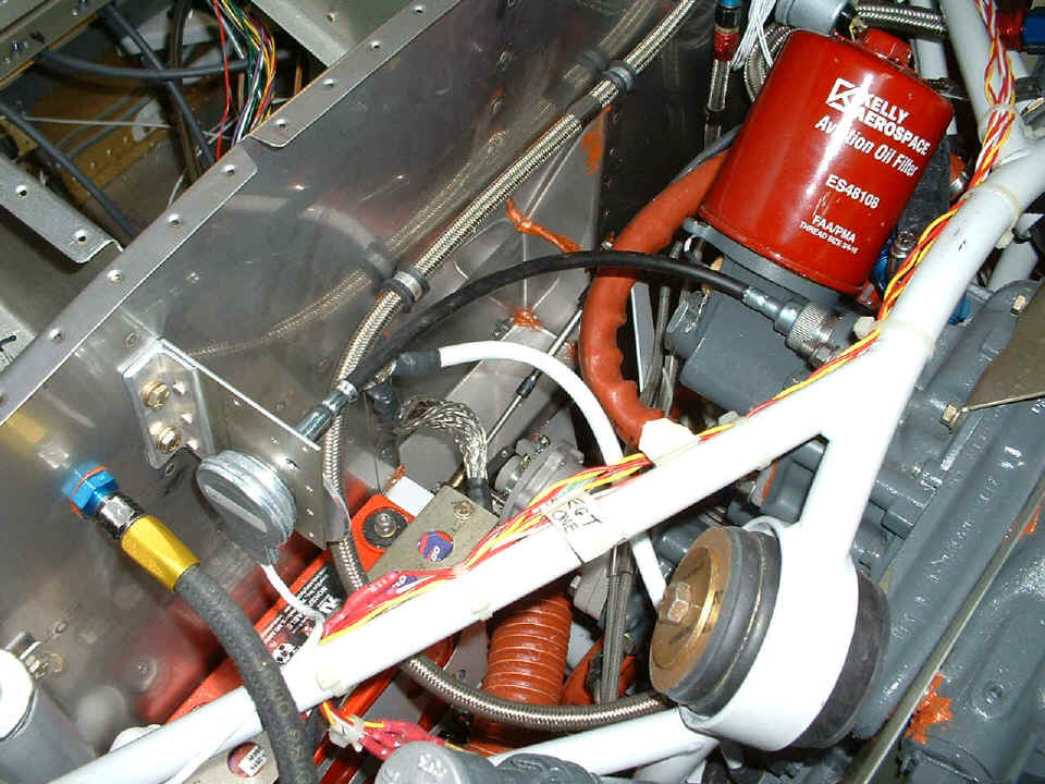
RIGHT! The nut on that new black tachometer cable would not clear the right-angle
oil filter adapter. I had to take off the oil filter and the adapter from engine
accessory case to start the nut on the tachometer cable port. Of course, when it
came time to secure the adapter to the accessory case, one of the bolts would not go back
without using a "claw foot" wrench on the 7/16" head of the one bolt that
could not be tightened properly with a combination wrench. I did not own any
claw-foot wrenches until I went to Sears at 8 PM this evening and spent $43.69 for a set
from 3/8" up to 1". All four bolts of the oil filter adapter are secured
now. At the end of that 12-inch tachometer cable is the tachometer sensor that produces
the pulses needed by the EIS engine monitor to display engine RPM. I will have to
fabricate a bracket to attach it to the firewall.
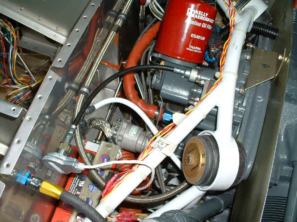
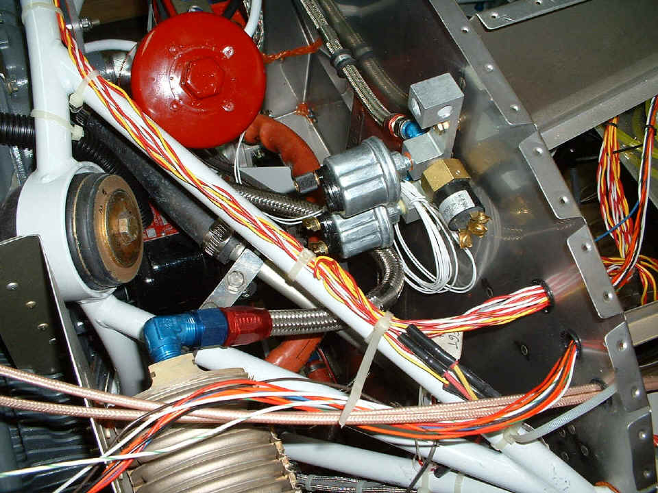
The other "easy installation item" in tonight's work session is the
oil pressure switch that runs the HOBBS digital hour meter anytime there is more than 15
PSI of oil pressure. When the oil pressure is less than that, a light will come on
inside the cockpit when I get it wired up. The pressure switch needed some clearance
from the firewall, so the bolts got changed to some that were a bit longer with flat
washers between the pressure sensor manifold and the firewall. The other thing that
is new in the photo below is a bit hard to see. I put an Adel clamp around the
aluminum vent tube from the crank case, and another around the engine mount pipe right
below that large BLUE right-angle fitting on the oil cooler. There is a metal strap
between the two clamps to keep the rubber hose from the engine accessory case from
contacting the side of the oil filter. I am starting to think more about vibration
of everything after seeing David Edgemon's airplane this past Saturday. I can see
many things in this photo and the others that will have to be reworked with
"anti-chafing" tape, etc.
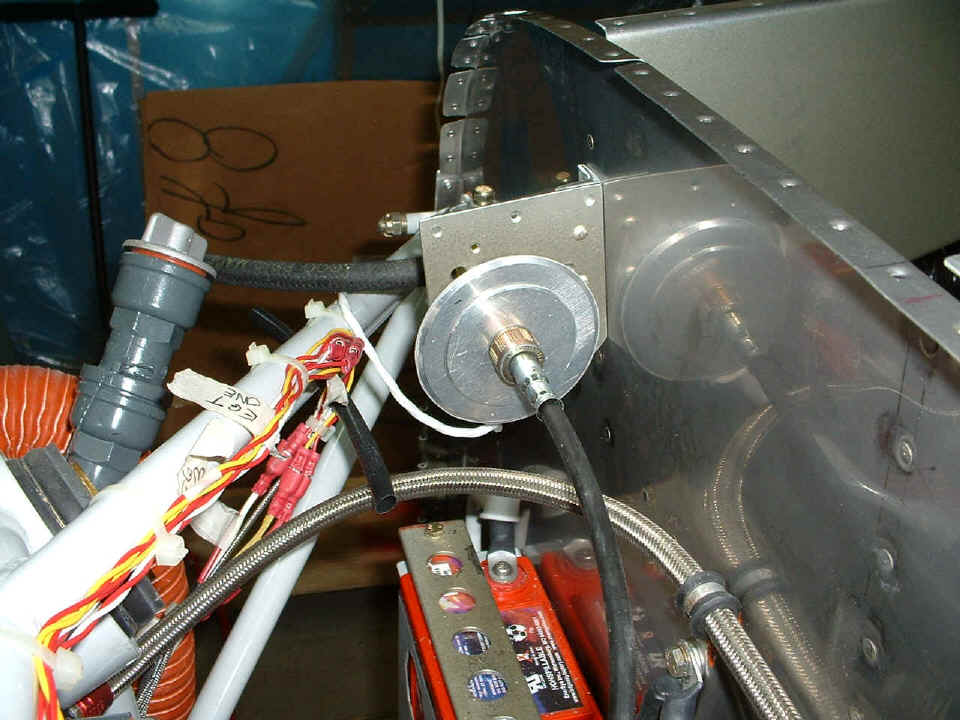
I went through the scrap metal pile and found an angle that I had discarded
from another task, and a doubler plate that did not quite come out right for the electric
fuel pump. Together with some "cut out" circles from the road sign
instrument panel, I found the way to secure the tachometer sensor on the front flange of the
F7107R rib and the firewall. The angle was cut a bit shorter and drilled out to
accept 3/16" AN-bolts, then riveted to the doubler plate with three #4 rivets.
I used two bolts, washers, and Nylok nuts similar to the method of mounting the pressure
sensor manifold on the other side of the engine compartment to secure this bracket to the
firewall.
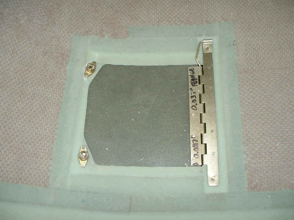
The other side of the tach mounting plate shows two of the three spacers I
made from the cut-out plugs from the instruments on the instrument panel. I needed a
spacer that was 0.3125" thick with a 5/8" hole in it. Using three of the
plugs and another piece of 0.062" plate gave the correct spacing. Everything
is
secure and ready to wire up to the EIS engine monitor.
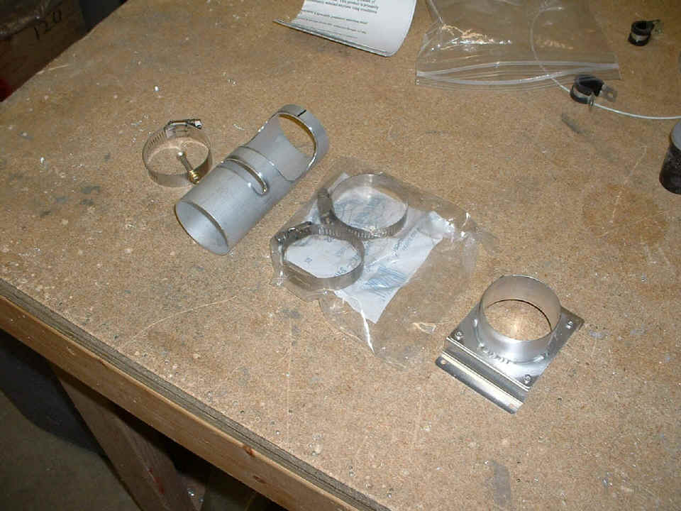
Here are the carb heat muff and the air vent that goes on the top of the
filtered air box (FAB). I bought the two stainless steel hose clamps at Lowe's when
I went out to get groceries just after 5 PM. I will use a short piece of the red
heater hose seen in photo above to make the connection from the muff to the vent on top of
the FAB. This stuff will have to wait until I can get the FAB built. You can
see how David Edgemon did his by CLICKING on this LINK.
The other news of the day was the mail arriving with my FAA aircraft registration forms. I will be sending them back tomorrow after getting the form 8050-88 notarized at my bank before the mail goes out at 5 PM. That is the form that certifies that I build over 51% of this airplane. In my case, it is 100%. I had some help on some of the rivets where I could not reach both sides with the gun and bucking bar at the same time, but I was on one side or the other of every rivet, bolt, nut, and screw in the airplane.
December 3, 2004: No work on the airplane today, but the FAA aircraft registration forms were mailed to Oklahoma City. I got emails with tracking numbers on my Dynon D-10A which is shipping from Washington State, and also another shipment from Van's Aircraft with the strobe lights and the red and green wing-tip marker lights.
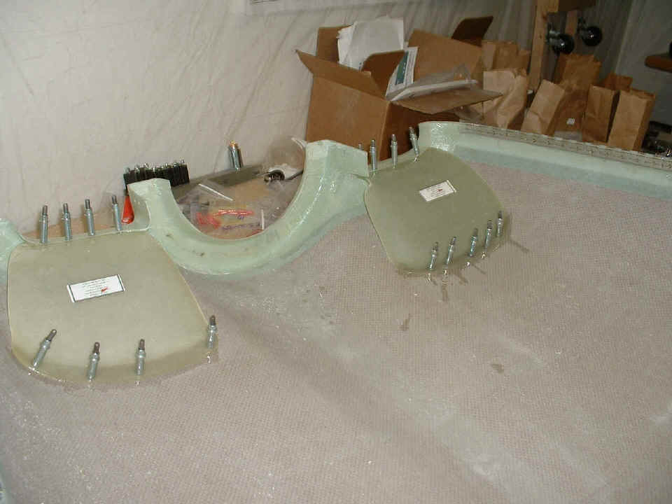
December 4, 2004: Saturdays are usually good
days to get a lot done if I am not off flying or visiting another RV builder. This
day was a day with a lot accomplished. The day started by mixing up my first batch
of epoxy and putting the upper air inlet ducts in the upper cowling on my work bench.
You can also see that the side hinge at the right side of the photo is riveted in
place. I drilled holes in between all the rivet holes allowing some of the epoxy
that is also there to bleed through for a better bond of the side hinges. Both sides
are done this way.
Next came a repair to one of the camloc fasteners which I had put in at an
angle not thinking about how the top of the handle would look from the outside. I
drilled out the two rivets and filled the holes with epoxy. Before doing that, I
confirmed that when it is time to drill the new rivet holes, that I would have virgin
fiberglass to accept the new rivet holes. I will also have to grind away from the
excess thickness of the fiberglass from the factory molding of the area where the fastener
needs to be located. You can also see how I secured the end of the rod in the hinge.
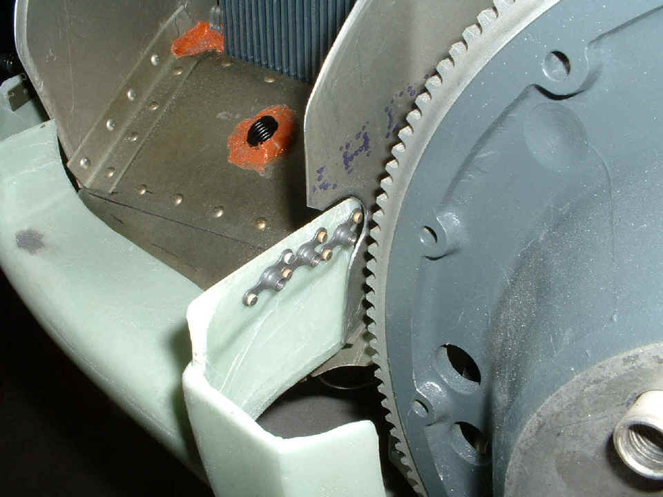
The last picture for this page shows some trimming I did to clear the platenuts
on the lower cowl from the baffles on the right side of the ring gear. I had to do
this to the other side also.
| CLICK HERE for Firewall Forward page 73. | RETURN to MAIN MENU. |