FIREWALL FORWARD - Page 65.
November 16, 2004: The past few days have
been a bit tedious working on the engine cooling baffles. I wanted to wait until I
was finished to post any more pictures. I feel that I have completed all the rivet
holes and trimmed off any excess material where appropriate. Here are the pictures
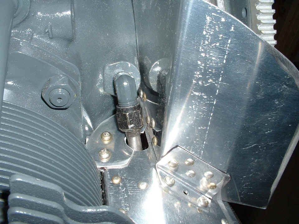
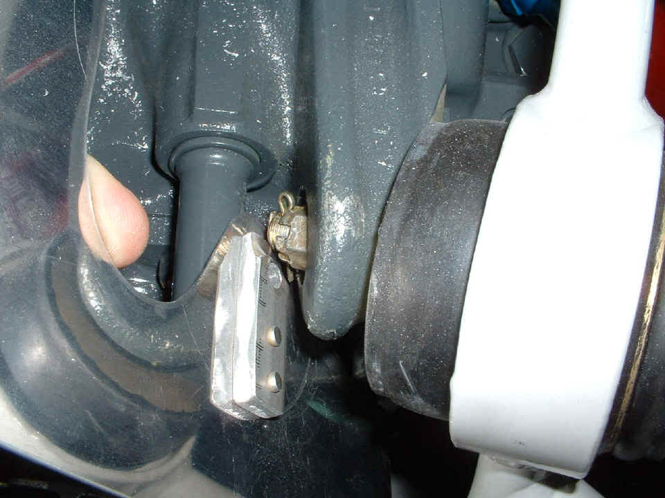
that are significant over the past few days. The first one shows the high-pressure
oil line that controls the propeller pitch angle. It is a stainless steel line that
I did not want to disconnect. I made a metal plate (twice) to wrap around it leaving
a small gap that will be sealed with red high-temperature RTV silicone to prevent an air
leak. Because this piece was so hard to get on and off, I decided not to rivet all
the pieces together as spelled out in Van's baffle kit instructions. I have used
number eight screws and platenuts where I thought it was needed. This first photo is
looking from the cylinder head of the number ONE cylinder toward the crankshaft. The
ring gear is visible in the top right corner of the picture.
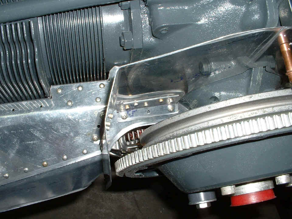
This photo is of the same area shown from a different angle from above the
engine. Another view shows where I installed platenuts and number eight screws
instead of hard rivets. When this is finally attached for the last time, there will
be plenty of that RED RTV silicone visible.
Here is the first of the little flange doublers to be riveted in place on the
baffles that wrap around the cylinder cooling fins. There is a #40 hole in the
flange and doubler for a safety wire that will tension these flexible parts of the baffles
firmly against the fins. I trimmed one of the flanges to clear an oil return line
going from the cylinder head to the crank case oil sump.
The next photo shows a 1/4" thick finger doubler that was called out in
Van's baffle instructions. I later found that it needed to be ground off on the end
to allow the baffle plate to be installed when all three major parts are riveted together.
The photo below this one shows the details.
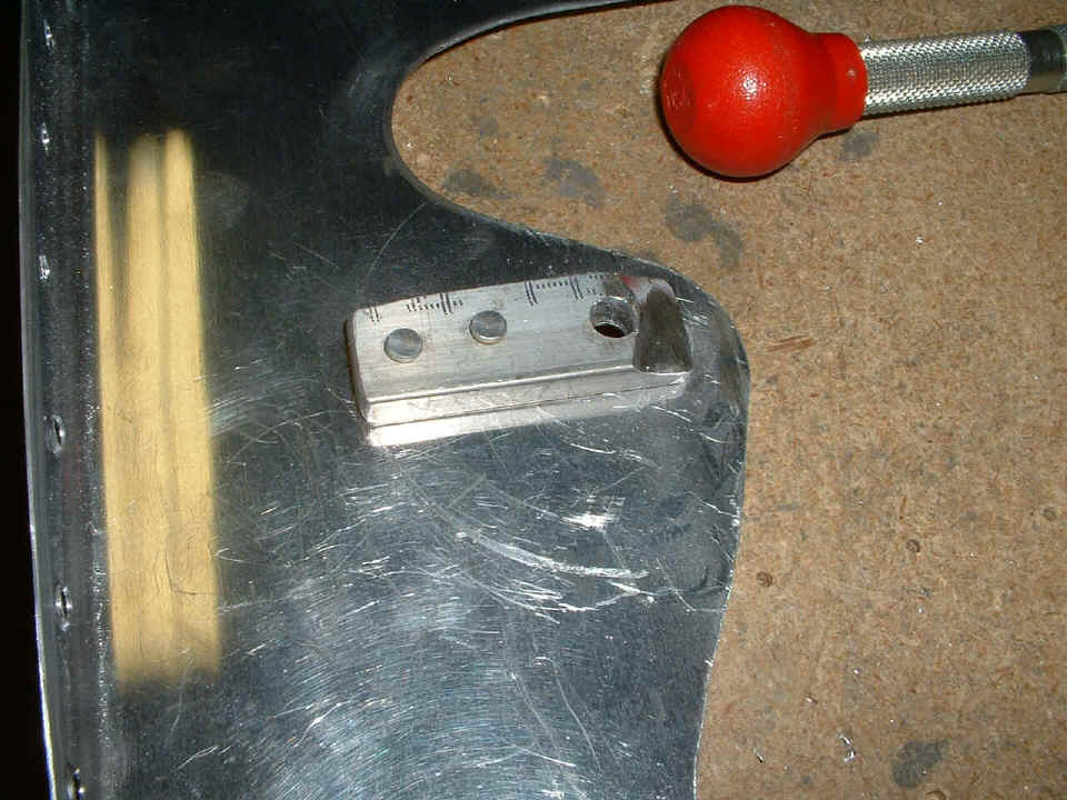
Does this make it clear? That aluminum finger spacer (not my finger) has
to pass by the upper left engine mount bolt when the baffle is installed. This
baffle is at the rear of the number FOUR cylinder near the oil cooler.
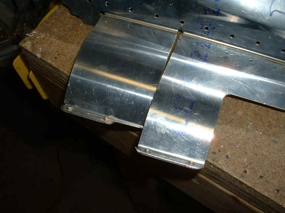
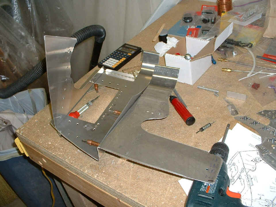
Here is that part from the photo above sitting back on the bench and clecoed
together with the other two main baffle components for cylinder number FOUR and the oil
cooler area. Once this is all riveted together, it has to be installed in one large
assembly. I was verifying that it would all go on the engine as one assembly when I
found the need to grind down the end of the finger spacer discussed in the two photos
above this one. That piece at the far right side of the photo is the front plate
that was shown in the first photo at the top of this page. It is upside down in this
photo showing the platenuts that hold the front upright baffle plates to it.
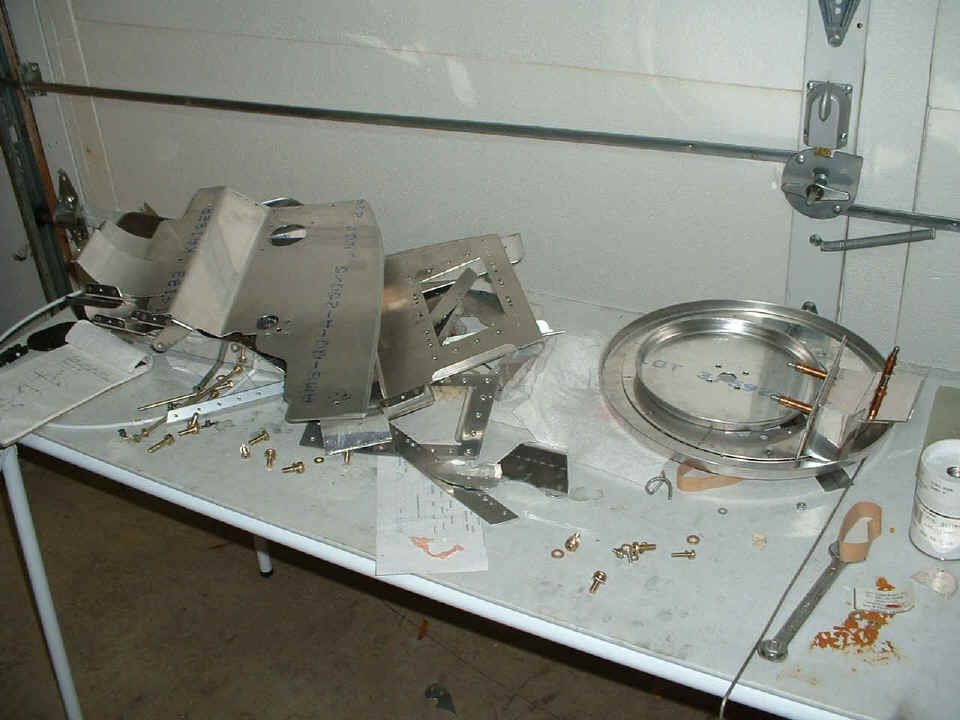
The last photo of the day shows all the parts in a pile ready for a priming
session when the weather permits it. I still have a few more bare aluminum parts to
take off the engine before the priming session. I also managed to finish running the
spinner plates and doubler past my 1-inch Scotchbrite wheel on the drill press to smooth
up some rough edges.
The latest spread sheet statistics show about 35 hours of work on the engine cooling baffles. The overall project total is now 1394.3 hours. The actual time worked on the airplane is 1325.3 hours.
| CLICK HERE for Firewall Forward - Page 66. | RETURN to MAIN MENU |