FIREWALL FORWARD - Page 64.
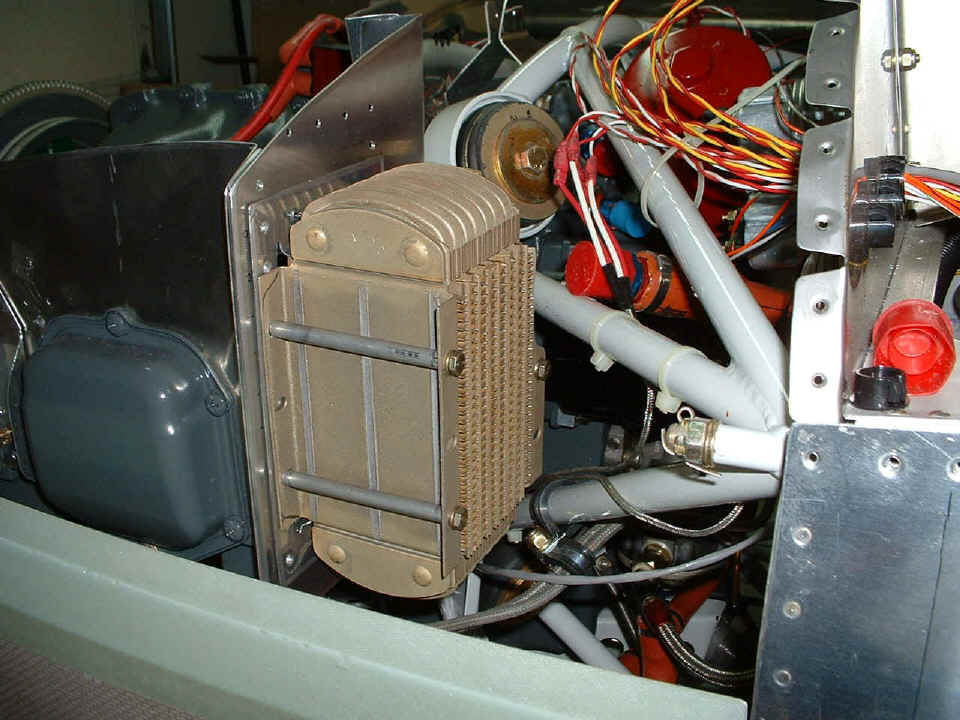
November 8, 2004: This evening's chore was
to get the oil cooler mounted at the correct height. And here it is after correcting
for the holes that were drilled prematurely in the back baffle plate. The four
mounting bolts and the platenuts are holding everything together as no rivets are
installed yet. The earlier row of rivet holes near the top of the baffle back plate
will be easy to cover using the fabric that seals the baffles to the inside of the
cowling.
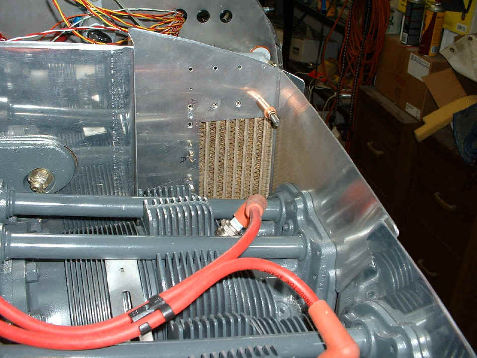
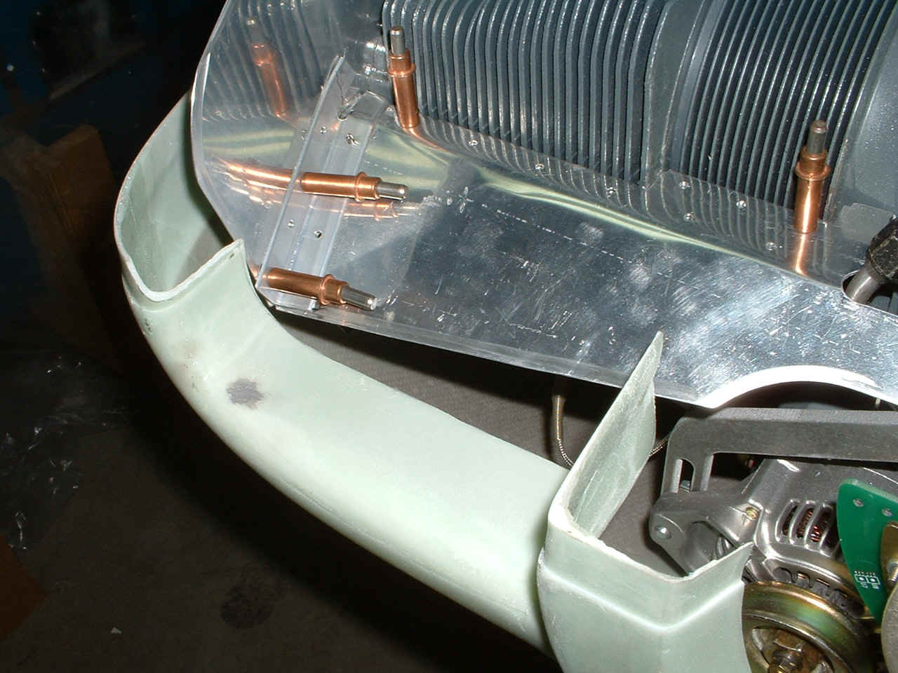
Here is the view from the front of the oil cooler. It is sitting down
behind the cylinder by about 1.5 inches. There is at least one rivet hole that will
need to be filled since it is below the level where the flexible seal will be attached to
the back plate.
I took some time right before quitting for the evening to trim the other back
plate down to clear the cowling. Of course I had to check the clearance of that
baffle plate by putting the cowling in place. The upper cowl is clear of the back
plate behind cylinder number THREE on this side of the engine. I have marked the oil
filler/dipstick access door for cutting in the next session. I can use that opening
to better see the clearance of the rear baffle plate below the upper cowling.
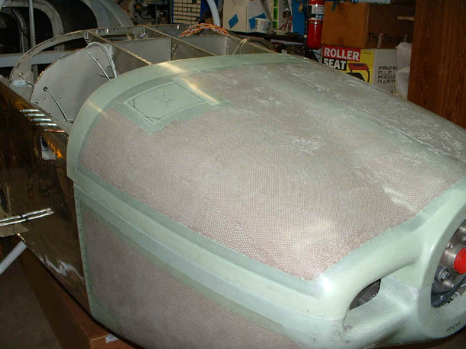
Although it does not show in this photo, I have ground away the excess fiber glass
from the lower cowl in the air intake shown in the photo above. I will have to put
the forward skin on temporarily when I am ready for the final cut and fit of the upper
cowl. The aircraft construction time stands at 1302.0 hours
after tonight's session.
November 9, 2004: A few more pictures of tonight's
work on the baffles. I cut down the height of the two RIGHT side baffles on
cylinders 1 & 3 and cut the right angle brace to length.
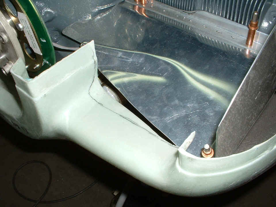
Up in front of cylinder #1, the "floor" baffle that directs the air
flow up over the cylinders on the right side is being put into position and braced.
The side baffle on cylinder #1 is bent inward toward the air intake per the plans.
You can see that I have removed the ring gear now that I know how much clearance there is
around it. A piece of flexible air seal material will bridge the gap from the air
intake to the floor plate.
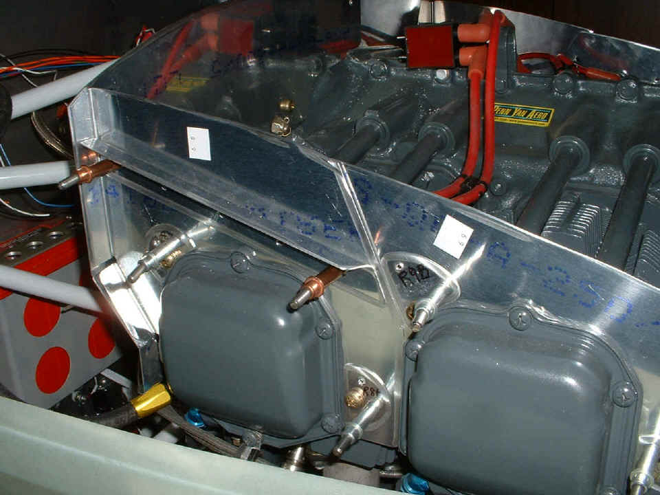
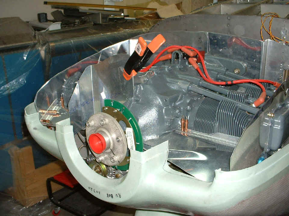
Here is the view on the other side in front of cylinder #2. I have marked
the area of the fiber glass that needs to be trimmed on this side. I find that my
Dremel tool with the sanding drum is best for working with the fiberglass. I have
not yet bent the side plate inward toward the air intake.
The last shot of the airplane tonight shows how the back wall panels are cut to
what should be the correct height under the upper cowl. The clamp at the front is
holding one of the front plates in place. I have to fabricate two angle braces to
hold the plate shown to the floor plate on the left side of the photo. And of
course, the process will be repeated on the right side of the photo in front of cylinder
#2.
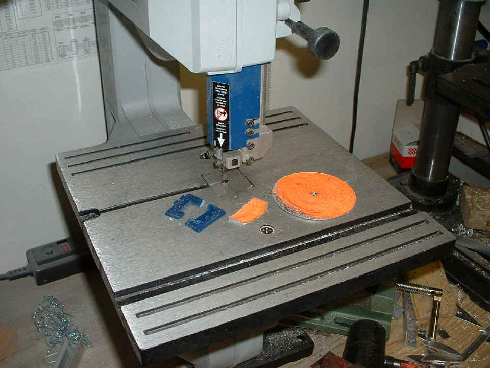
And tonight was the night I had to do a minor repair to the band saw. It
seems that there WAS a plastic plate in the table surrounding the blade. When I
would run various aluminum parts through there, they would heat up and melt the plastic.
It finally broke tonight and I had to make a replacement from aluminum of course!
The best piece of scrap that I had that was the right thickness came from the
cutouts from the "road sign" instrument panel. I started with a round disk
like the one in the photo and cut away enough of it to leave the rectangular piece that
replaced that broken blue plastic. The Scotchbrite wheel made it easy to get the
aluminum plate to the correct dimensions. And yes, I left the ORANGE color
on the bottom
side of the new part.
Put another 4.7 hours in the log book and good night all.
| CLICK HERE for Firewall Forward - Page 65. | RETURN to MAIN MENU |