PANEL WORK & WIRING - Page 57.
October 2, 2004: The mail man dropped off
another small package from Aircraft Spruce & Specialty today with the panel mount
Master Switch inside. I bought a genuine Cessna RED switch to turn on the Alternator
field current and the master battery relay. The MAG/Starter switch has not come from
Van's yet. I used one of their online photos to estimate the full size given the
mounting hole size of 7/8". I then made a quick layout of the switch panel and
put some holes in it. When I finished, I had to put it in place for this ONE photo.
I won't paint it until I get the other switch and get its mounting hole drilled.
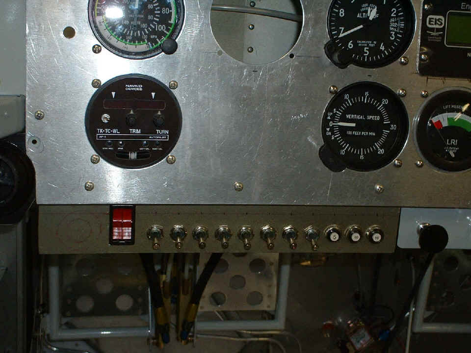
You may see a faint line in the photo above about 1/2" up from all the toggle
switches/breakers. That is the limit of my visibility from eye-level when sitting in
the seat. That tells me how high to make my labels and where to center the switches
on the panel. The red circles on the left represent the 7/8" mounting hole and
the overall size of the MAG/Starter switch when it gets put in place.
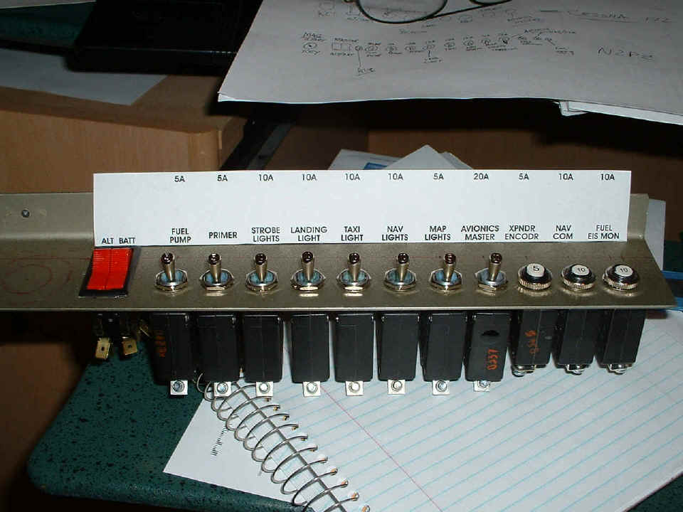
Here is the first cut of the label I have made for the switches. I will
have to see if I can get a good clear sheet that I can put through the laser printer to do
this better. For now, it is printed on plain white paper. And yes, I see that
I put the 20-ampere switch/breaker in upside down. Everything has to come out before
drilling the last big hole, then painting it gray.
I had two pilot visitors today who were interested in learning about home-built
aircraft and the Van's models especially. Dave Homan is
an internet flight simulator forum acquaintance that I finally met face-to-face for the
first time today. He lives south of Atlanta in the Peachtree City area. He
recently passed his check ride for his private pilot license and had planned to fly up
here today, but the limited visibility was not due to burn off until noon time. Dave
stopped by Canton, Georgia on his drive up to the Chattanooga area to pick up a friend and
student pilot, Scott Shaw. Scott just recently soloed
and has just over 20 hours in his PPL log book on his way to getting his check ride very
soon. I gave them the full story on the RV-9A and showed them some of the things you
have to learn to build one of these. We had about 2.5 hours of time in the shop
before getting a late lunch so that they could get back to the Atlanta area at a
reasonable time.
October 3, 2004: More wiring today -- but first, the news from TEXAS! My son Edward made
his first unassisted landing in a Cessna 172 today. The instructor had him doing
power-on and power-off stalls at altitude and working under the hood for basic instrument
training. After doing slow flight at altitude and "flaring" for a
simulated landing, they made the approach and he "greased it in" on the runway
at Georgetown, TX. To say that he was high on adrenaline when he called on his way
home from the airport is an understatement!
Back to the work at hand: I connected the P1 wire to the master switch
solenoid output side. The three-ampere damper diodes were also installed across the
solenoid coils of the master and starter solenoids. I wired the DPDT center off
momentary switch to the flap motor after securing the other end of the motor to the flap
actuator arm. I wired up a ground wire and the master solenoid coil wire to the
panel-mounted master switch. Then I tested the flap motor for up and down
movement. Notice the conduit to keep the wiring neat as it grows more dense.
This conduit runs to the firewall access port near the solenoids and battery. The
big #8 wire is the main B+ line from the master solenoid. I have it temporarily
connected to the 5-amp circuit breaker for the flap motor. Only the battery side of
the panel-mounted master switch is wired for this test.
Here is a look at the wiring attached to the solenoids. I have the large
white insulating boot pulled back on the battery side of the master solenoid to make it
easy to attach my charger when needed. I tested the starter solenoid and the starter
motor with the ring gear removed from the engine of course. The MAG/Starter switch
is not here yet, so there is no connection to the starter solenoid coil until that switch
is installed.
October 4, 2004: The mail arrived from Van's
Aircraft with the MAG/starter switch and the 60-ampere circuit breaker for the alternator
output. I put a 3/4" hole in the switch panel using my unibit, then enlarged it
to 7/8" with my large deburring tool to accept the starter switch. I printed a
revised switch/breaker label on plain paper with my laser printer and put two plies of
clear adhesive tape over it and stuck it to the freshly painted switch panel. I
decided the black on white label would be better than black on gray if I went out and
bought some clear adhesive film and printed that in the laser printer. I took this
picture from "eye level" to show what I see while sitting in the LEFT seat.
The two white wires hanging down go to the flap motor. They will be bundled
up with other wires and kept up behind the switch panel when completed.
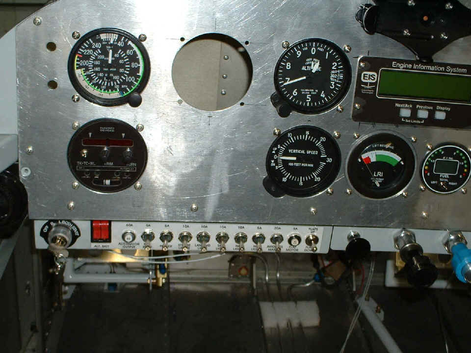
The switches from LEFT to RIGHT: Ignition
switch, master switch, 60-ampere alternator circuit breaker. The combination
switch/breakers continue across the panel with a 5-amp unit for the electric fuel pump, 5
amps for the primer solenoid, 10 amps for strobe lights, 10 amps for a landing light, 10
amps for the "taxi" light (I may combine these later), 10 amps for NAV lights, 5
amps for interior map lights, and 20 amps for an avionics master. The push-button
near the right end of the switch panel is a 5-amp breaker for the flap motor with the DPDT
momentary center-off flap switch at the right end next to the BLACK carb heat knob.
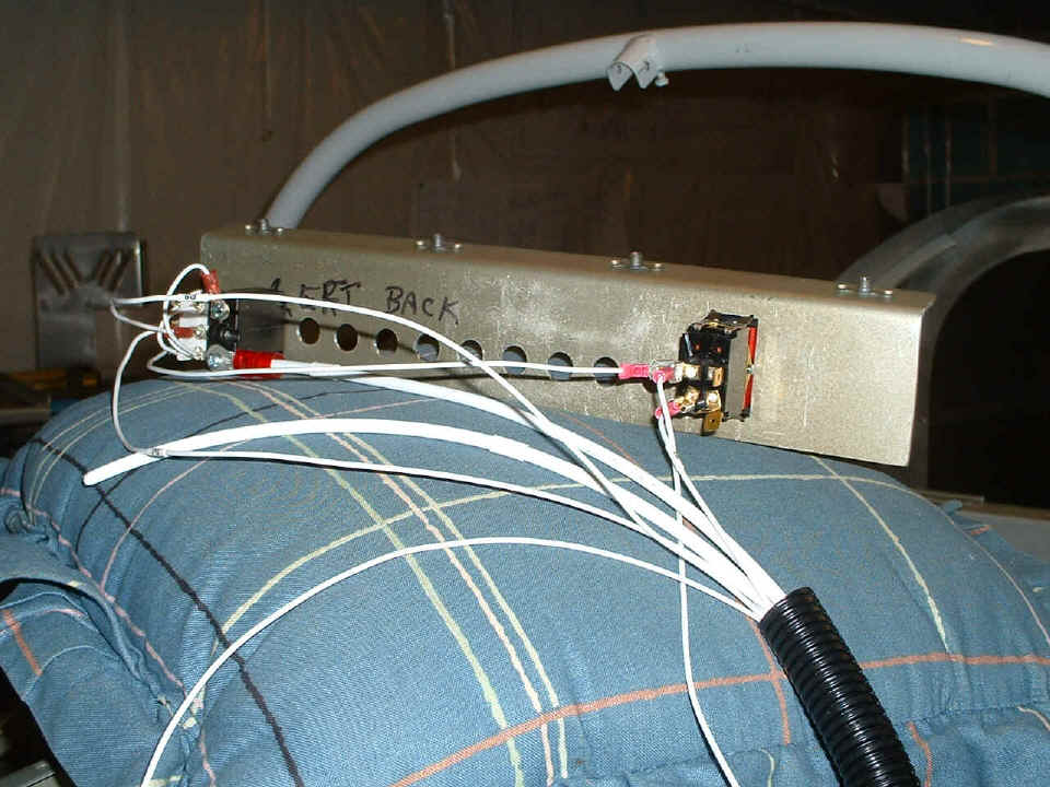
Here is a view behind the panel showing one of the half-inch
wide copper bus bars provided in Van's wiring kit. I put it directly across
one terminal of ALL the breakers and had to put a twist in it to mate up with the WHITE
60-amp breaker from the alternator. What you don't see are the big lugs on the ends
of the #8 wires coming from the alternator output and the battery via the master solenoid
contacts. The battery connects directly to the bus bar at the bottom terminal of the
60-amp breaker, and the alternator lead comes to the top of the 60-amp breaker at the far
right (under the wing-leveler) and then to the copper bus bar through the 60-amp breaker.
The #18 wire connected to the lug on the bus bar near the right end goes to the
BATT terminal on the starter switch to activate the starter solenoid when needed.
All those empty screw terminals on the top of each switch/breaker will get a wire
connected as the light circuits and avionics are added. The black one with the RED
date code letters on it is the 20-ampere switch for the avionics master. Since the
5-amp breaker for the flap motor is a different type, I had to make a short #18 jumper with
lugs crimped on each end to connect it to the bus bar.

The two white wires go to the flap motor and will be bundled with tiewraps
along
with all the other EIGHT wires when they are installed. When the Dynon D-10A goes in
here, this view of the switch bus will be blocked. The nice part is that the whole
switch panel comes off with just FOUR screws for easy wiring and maintenance. I can
easily strip off the label and change it if needed in the future. Of course that
would mean taking all the circuit breakers out of the switch panel!
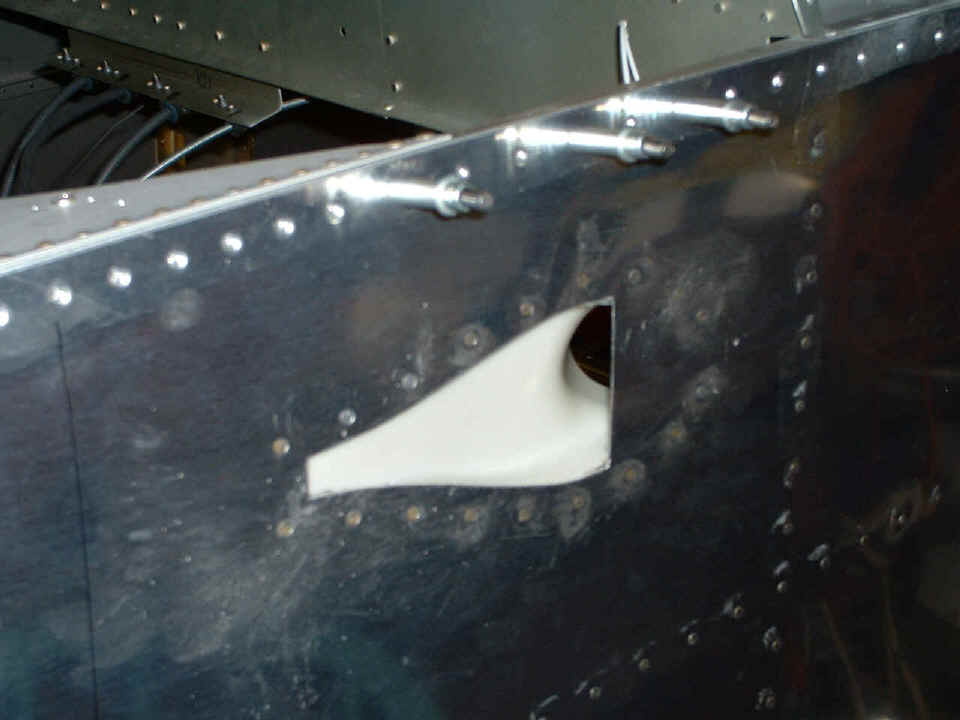
I finally decided to install the fresh air scoops now that I know how the
electrical conduit is going to move around behind the panel. I put on the LEFT scoop
with RTV to seal it to the inside of the fuselage skin, then riveted it in place. I
stopped for the evening before installing the scoop on the right side. I need to
clean off the excess clear RTV around the rivets and near the opening.
There is enough slack in the BLACK conduit and wiring behind the panel to allow
me to remove the switch panel from the bottom of the main instrument panel and work on it
in my lap when the airplane is finished. There is enough slack that I had it in my
hands outside the airplane where I stood to take the picture above when I was doing the
final assembly of the bus bar and all the switch/breakers to the switch panel. As
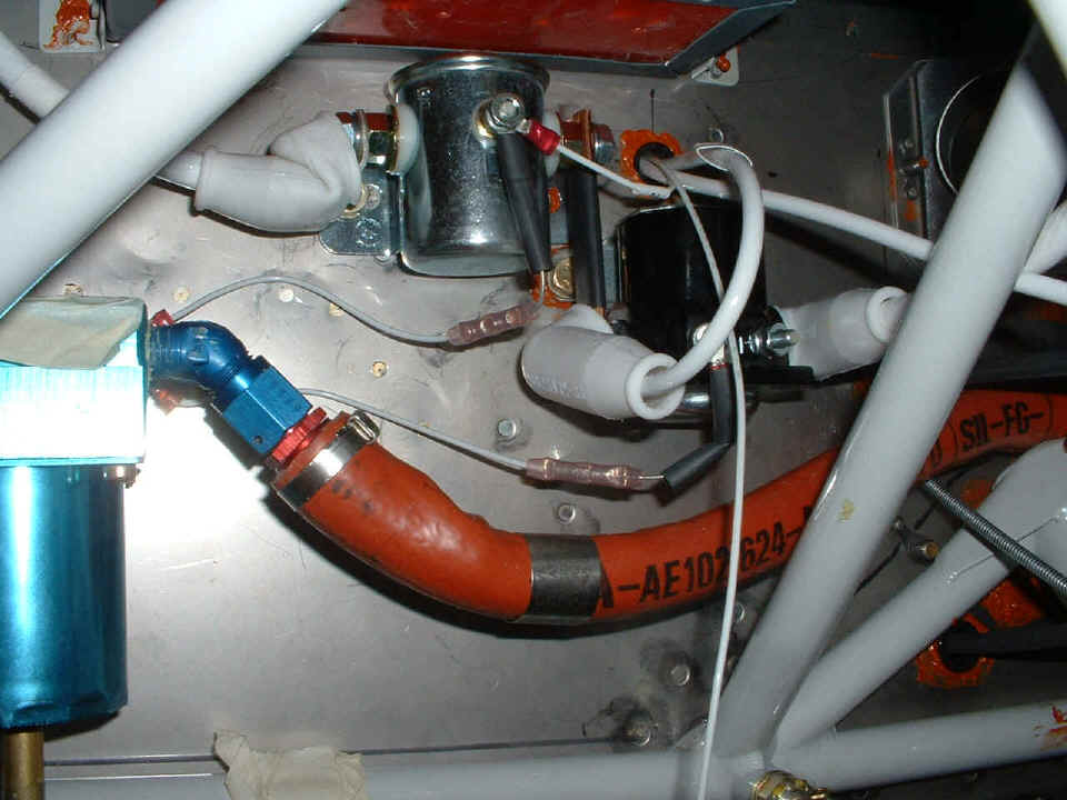
for the conduit and the fresh air scoop, they will get along just fine as you can see in
the photo below. The white scoop is visible on the right side of the photo with the
flexible corrugated conduit running underneath it. The white wire with the P3 label
on it is the remains of the original P3 wire from Van's wiring kit. I used it for a
ground wire to the switch panel and left it long enough to pull the panel into my lap to
work on it and have it still grounded. I will move this loop of #18 wire forward of
that bulkhead when the air duct is installed.
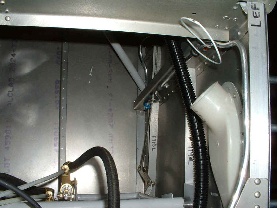
This photo is looking straight down into the forward fuselage area on the pilot's
side. The rudder pedal brake cylinders are visible at the bottom of the picture.
The LEFT steel rudder cable is visible along with the LEFT fuel tank vent line.
Aircraft construction time is currently 1247.6
hours. The total project time is 1316.6 hours.