Tugwell Canopy Modification - Page 2.
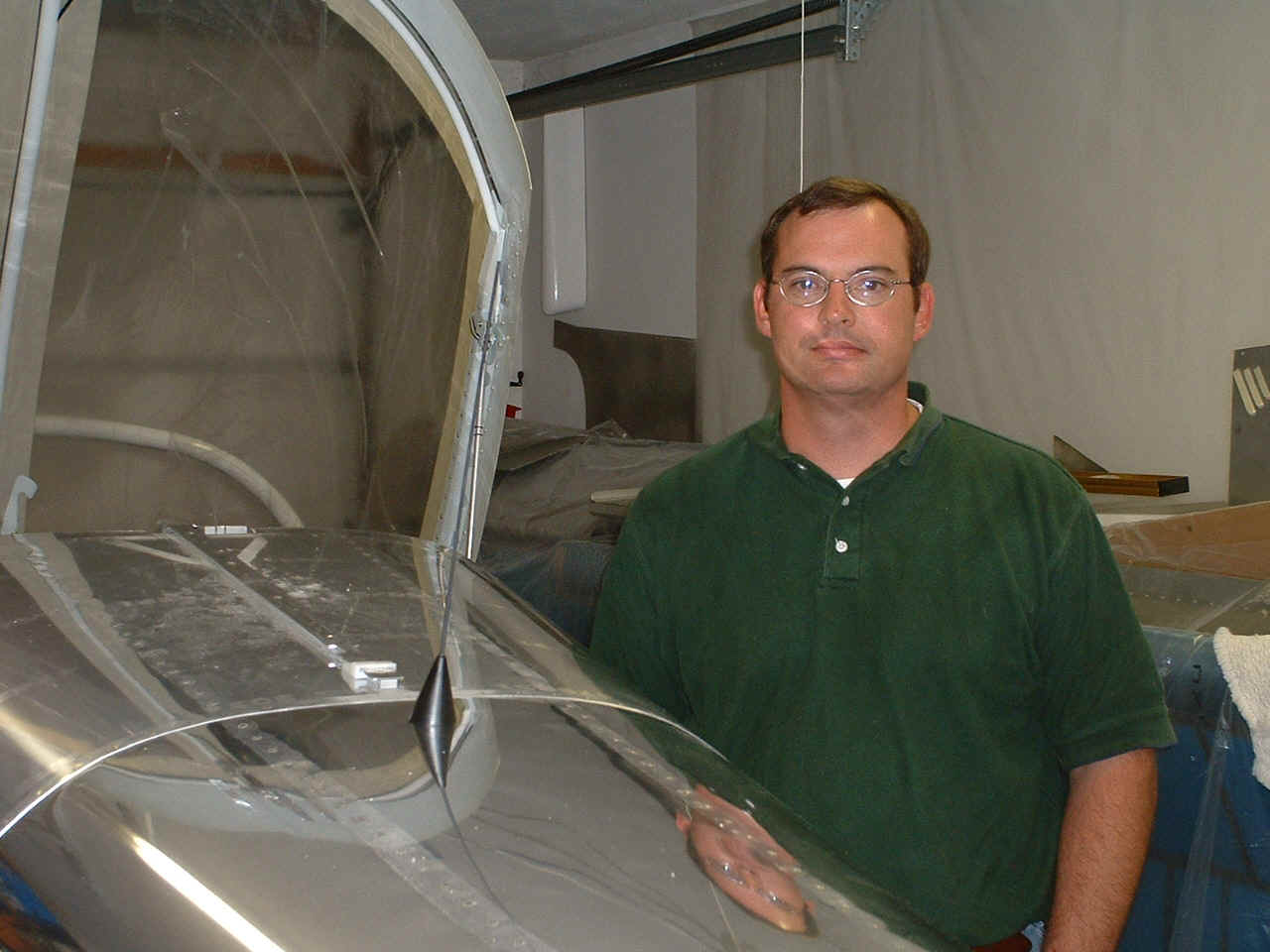
August 15, 2004: Finally, some work on the
airplane and some photos to show you all about the current status of my RV-9A under
construction here at "ye humble abode". As you can see, I have resumed
speed on adapting the Tugwell cable assembly to the RV-9 from its original design to fit
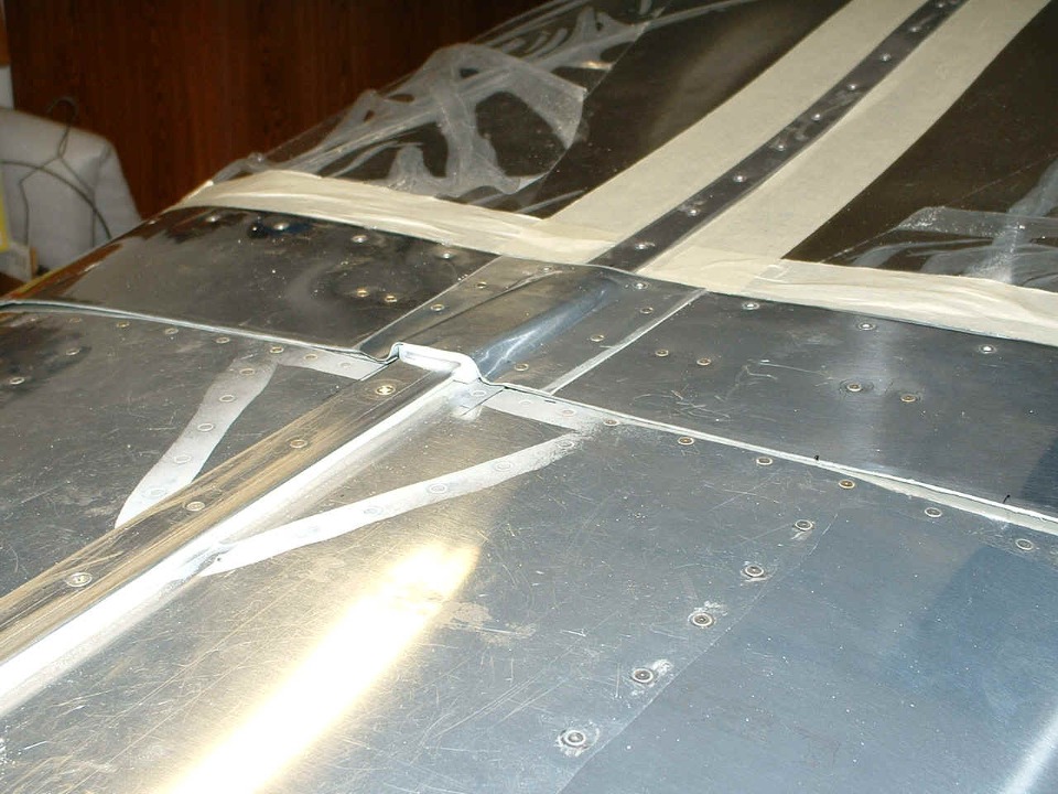
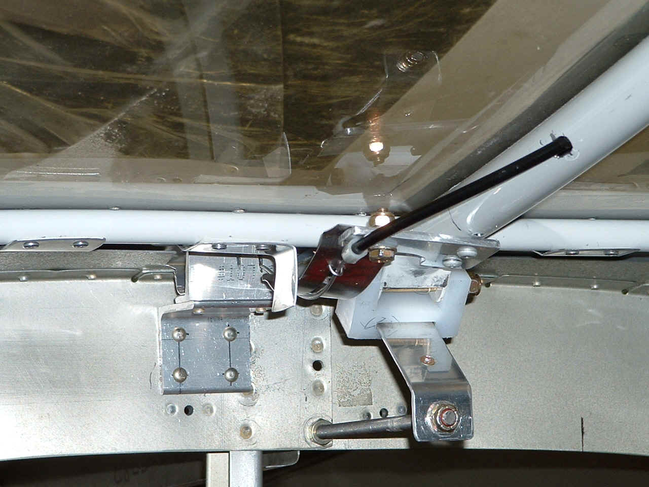
the RV-6(A) family of airplanes. I realized that the angle bracket shown in the
photo above was the same, and it clears just forward of the top fuselage skin in order to
engage the end of the steel cable. What appeared to be different in the RV-7/9(A)
canopy was the distance from the 4130 steel canopy frame tube seen in the photo below and
the lines on skirt which show the overlap point of the top fuselage skin behind the
baggage area. That distance is 2.625" (two and five-eighths). I think
this is a greater distance than in an RV-6. If that is true, then it could be why
another RV-9A builder had the same problems I did with this modification. I have
thought about this and have come up with a solution that appears to be working.
Here is what I have done to make the Tugwell mod kit work on
my RV-9A.
1. Cut a slot in the stainless steel strap along
the line of the cable movement, and installed a "wicket" using 0.041"
safety wire to keep the steel cable in the slot.
2. I have put a tab bracket of my own design
adjacent to the stainless steel strap to keep it from moving laterally away from the
canopy center line tube and therefore causing the steel cable to miss the notch in the
angle bracket at the baggage bulkhead. There are really only TWO
pop-rivets in the bracket. You are seeing a reflection of one rivet off of
the tab which is turned 90 degrees to the canopy frame aft tube.
3. The bracket also is riveted to the aft canopy
skirt to keep it down snug against the fuselage skin behind the canopy.
For RV-7 and RV-9 builders, I think it would be a good idea to install the
"L-shaped" tab above provided in the Tugwell kit closer to the rear of the
center tube of the canopy frame, and at the same time, reverse it's orientation so that
the black cable is closer to the angle bracket on the baggage bulkhead. When I
visited Robert Tugwell and inspected his prototype installation, I noticed the black
sheath for the steel cable passed immediately over the notch in the angle on the baggage
bulkhead -- probably within 1/8 of an inch above the notch. The black cable sheath
must be parallel to the center tube of the canopy frame when it passes through the clamp
that holds the cable sheath to the "L-tab". Grab the clamp with a pair of
pliers to twist it into alignment if necessary. You will only want to cut the notch
in the angle when you have seen the cable pass over the angle and have marked the location
where the slot should be.
Everything you see above is done because I blindly followed the instruction
sheet without knowing just what the relationship was between the black cable sheath and
the aforementioned angle on the baggage wall. That is why I say for new installs,
move the above "L-tab" closer to the back of the canopy frame. Before you
cut any of the black cable sheath off, be sure that you know that it is as close as you
can get it to the baggage angle and that it is not too long so that it would hit the angle
when the canopy begins to move aft (opening). The stainless steel strap normally
keeps the steel cable in the baggage angle slot as the canopy moves forward during
closing. The bend in the stainless steel strap near the aft end is to insure that
the strap will go up over the baggage angle when the canopy opens.
If you have already installed the Tugwell mod on an RV-7 or RV-9 and are having
troubles with a bent steel cable, you can try what I have done above. Your Dremel
cutoff wheel will wear down quickly while cutting the slot in the stainless strap.
Make sure that the slot in the strap is wide enough that it will not bind on the steel
cable that has to slide along the slot freely. If you need to replace the strap for
one that is a bit longer, contact Robert Tugwell. He provided me with a pair of
slightly longer straps for repairs on my mod kit. I also made the "Z-bend"
in the strap very short to maximize the remaining length of the strap.
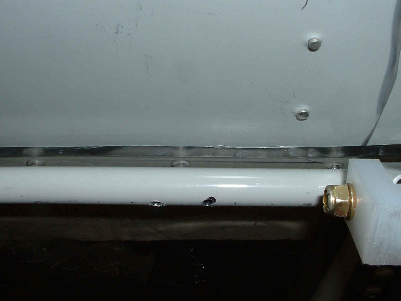
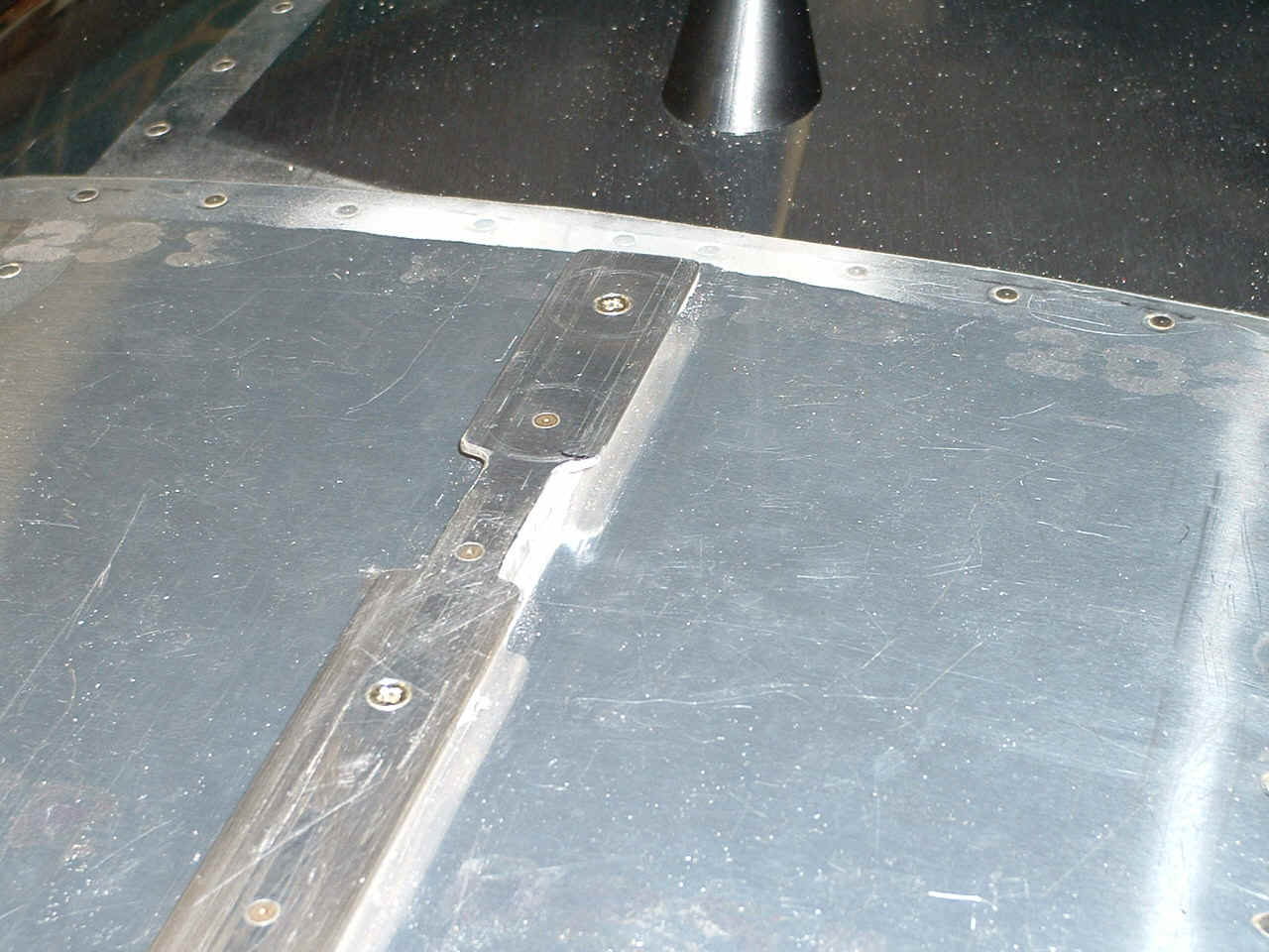
Now, the photo below shows where I drilled the holes to attach the brackets.
Notice that my new holes on the bottom are NOT directly in line with the hole on
the top side that holds the plexiglass to the canopy frame. This is a picture of the
LEFT side of the aft canopy frame and skirt and it is drilled the same way as the RIGHT
side where the bracket in the above photo is installed.
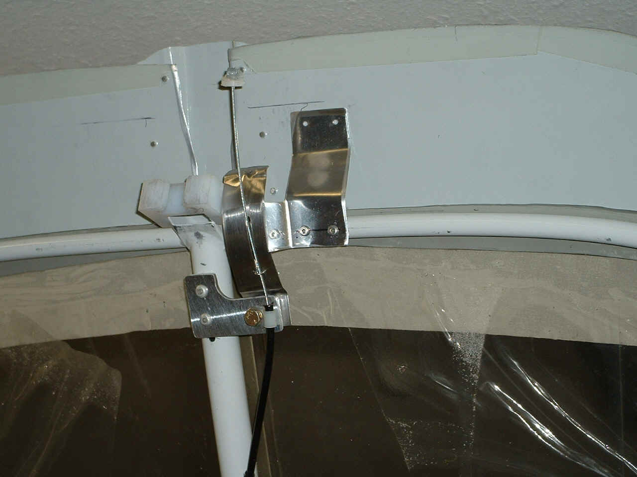
This view below shows the tab better and how it keeps the stainless steel
strap aligned in the proper direction. Make sure that your tab
is not too long causing it to hit the angle bracket attached to the baggage bulkhead as
the canopy is opened and closed. You can also see the safety wire
"wicket" better showing how it is fed through two 1/16" holes in the
stainless steel strap and then bent outward on the back side. There is less than a
1/16 of an inch between the stainless steel strap and the pivoting UHMW slider block shown
below. Notice that I have not drilled the holes through the aft canopy skin. I
planned to do this later with the canopy closed and the aft canopy skin pressed down
firmly against the fuselage top skin.
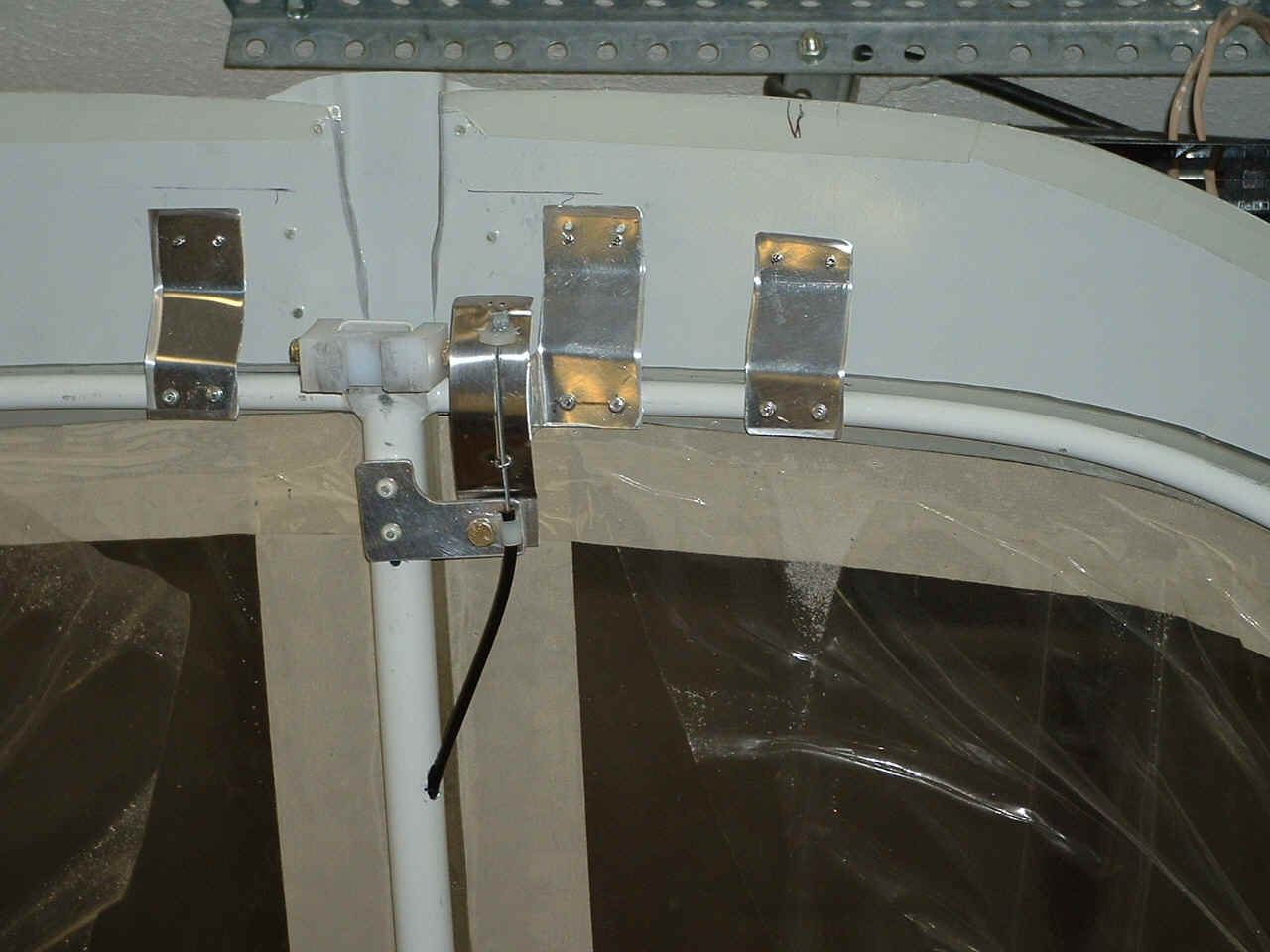
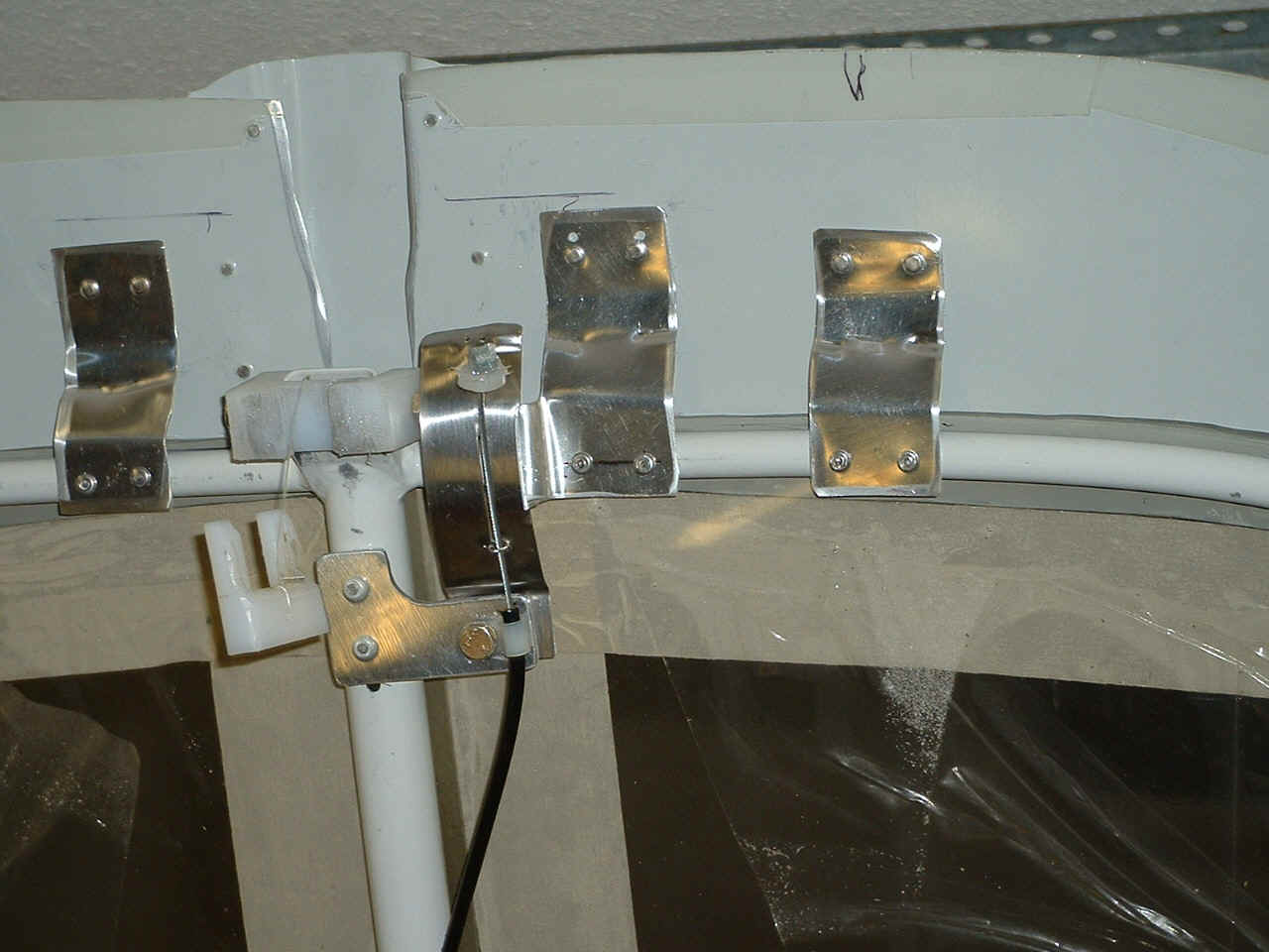
As you can see below, I ended up with three brackets to help keep the aft canopy skirts down against the
fuselage skin. Here they are shown riveted to the canopy frame tube after
they have been drilled to the aft canopy skirt and clecoed in place from the other
side. I noticed when I was inside the baggage area that the bracket holding the
stainess steel strap in alignment was very close to the baggage angle with the slot in
it. I therefore drilled two new holes further forward to insure the rivet heads
would not hit the baggage angle when the canopy is opened and closed. The cable is
retracted into the "open position" in this photo. The canopy latch handle
(not shown in this photo) is rotated about 180 degrees from the locked position, drawing
the steel cable to the position shown below.
Ray Johnson was helping me match-drill the holes on the aft canopy braces
(straps) that I used to hold down the aft skirt. He pressed down on the aft canopy
skirt with a wooden block to insure it was against the fuselage skin, then I back-drilled
up through the holes in the braces. You can also see the ELT antenna that I have
installed just aft of the canopy slider rail on top of the fuselage.
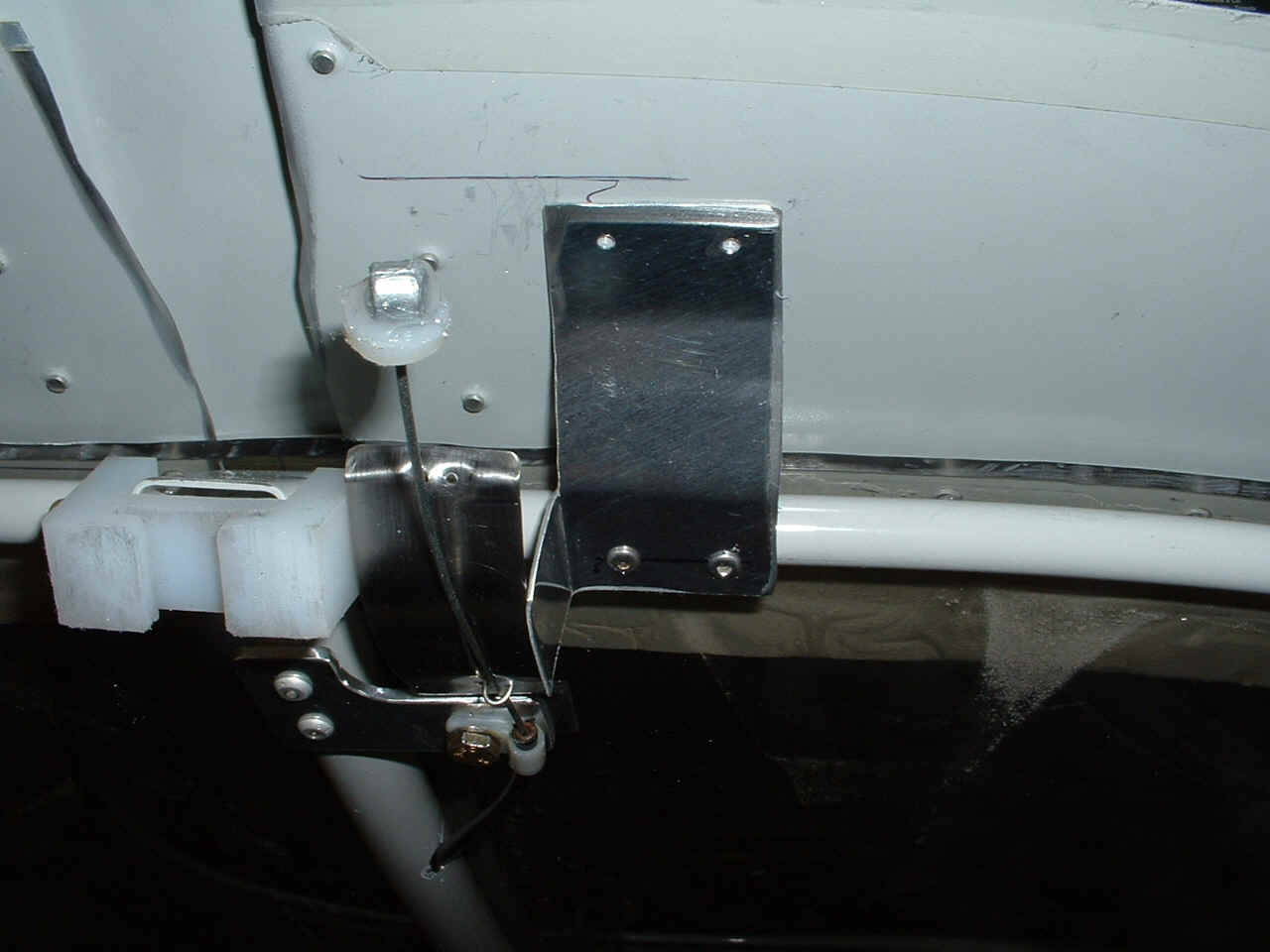
And here is the end result of my labors, the aft canopy skirt is laying flat
against the fuselage when the canopy is closed and locked. You can also see the
white UHMW plastic C-679 sliding plug that keeps the air flow around the slider rail to a
minimum (hopefully). Those hold down braces were needed because of the "dog
house" that you see there in the center of this picture. Each of the two aft
canopy skirts were laying nicely against the fuselage skin until I riveted the dog house
to the skirts. Then all three pieces raised up off of the aft fuselage skin.
So you see, all of this bracing was to make up for that little snafu -- and along the way,
I also helped the Tugwell cable-operated canopy opening kit work on my RV-9A.
Here is a view of the aft end of the canopy slide rail and the base of the ELT
antenna mount. I have enlarged the notches on the slide rail to make it easier to
get the Meske tip-up option working better
and to allow the C-679 sliding part to exit the rail when the canopy is raised to the
baggage loading/unloading position. I had to take the rail off the fuselage to
enlarge the notches on both sides. I used the large Scotch Brite wheel on my bench
grinder to do the job.
Here area all three of my braces now riveted in place. Notice the marks
from the fluting pliers. Yep, when I first match-drilled the braces to the aft
canopy skin, the skin did not pull down the way that I hoped it would. I realized it
was much simpler to just flute both sides of the brace straps and a bit in the middle to
shorten the straps and pull the aft skirts down as intended. After confirming this
had happened using clecoes, I then riveted the straps to the aft canopy skirts and here is
the result. The pop-rivets are LPT-3-4's. I used #3 solid rivets through the
straps and canopy skirts. The straps were made from excess aluminum trimmed off when
originally making the canopy skirts.
Here is the cable assembly and the baggage bulhead with the slotted angle
attached, shown with the canopy closed and latched. The stainless steel strap is
shown with a shallow bend according to Tug's original plans. As I said before, I
made the "Z-bend" near the "L-shaped" mounting tab as shallow as
possible to give more length to the strap. The safety wire "wicket is clearly
visible holding the steel cable in the slot I created in the stainless steel strap.
Notice the extra notch in the angle bracket. That was when I realized the
cable must go straight back toward the bulhead-mounted bracket with no lateral offset.
I was fortunate and did not have to remove the bracket from the baggage bulkhead
and install it closer to the centerline of the fuselage.
CLICK HERE for Tugwell canopy mod PAGE 3.
Return to Menu Page.