Wendell Folks RV-8 Project - Page 51.
May 2, 2007: It was a Wednesday evening
session with more work on the baffle air fabric installation. The front center
section and the addition of the last front side pieces of fabric were the issue tonight.
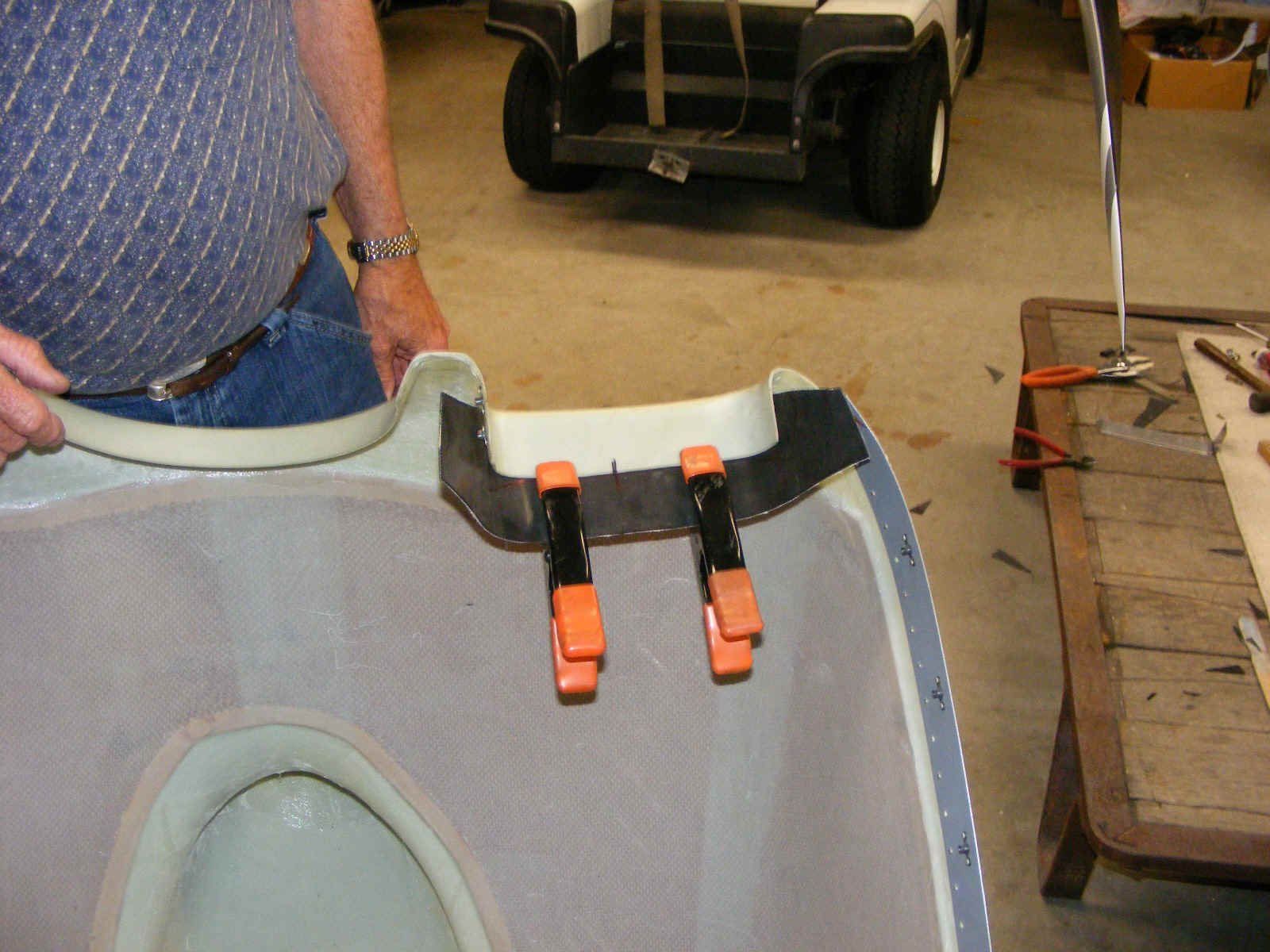
Before the session ended, I showed Wendell how to correctly fit the fabric to
the lower cowl air inlets. This fabric will overlay the front ramps of the baffle on
both sides of the engine. He had already made the aluminum straps that will go below
the fabric to "sandwich" the fabric between the fiberglass and the straps when
everything is riveted in place.
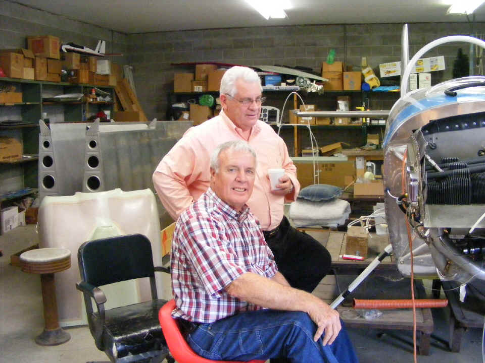
May 5, 2007: Saturday's
session also included a visit from RV-8 slow-builder Larry Champion. Larry stops by
from time to time to get a look at the next area of the fuselage he is working on at home
in his basement.
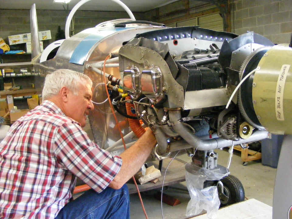
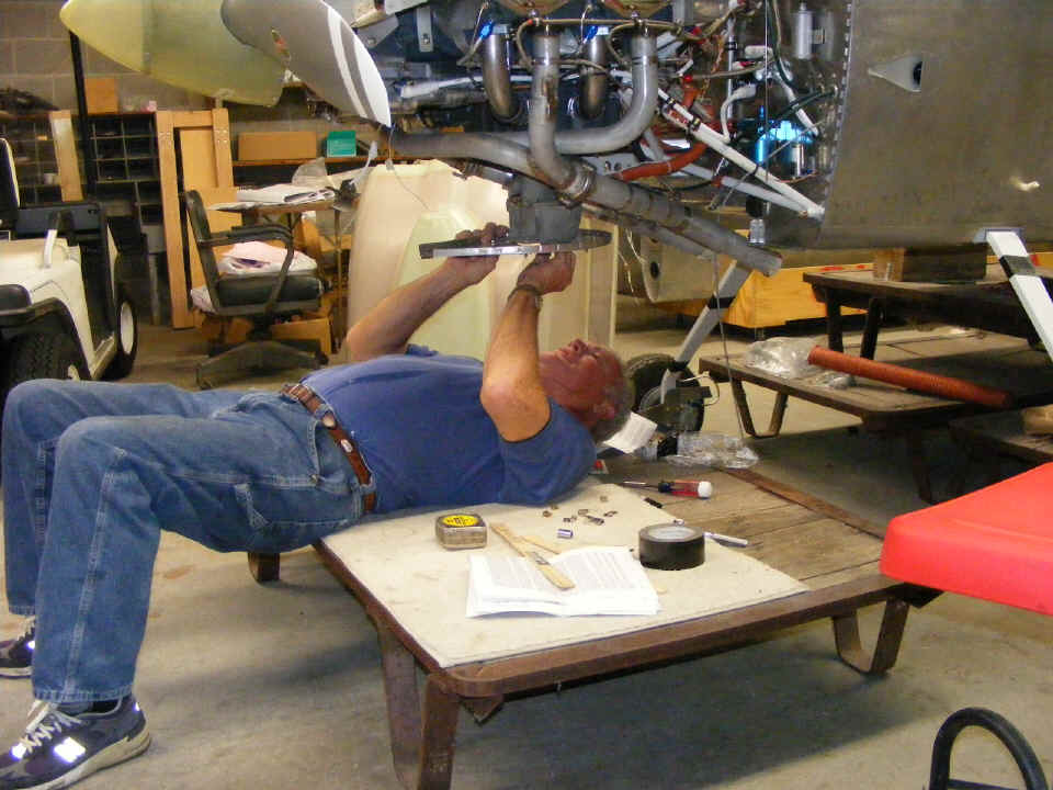
Wendell wants to get the cooling baffles completed so we can move on to the
filtered air box. The work today is to tie the pairs of curved baffles together to
finish routing cooling air around the cylinder head and barrel fins. I also checked
on the fit of the lower cowl inlet flexible air fabric before the lower cowl was removed
to allow the work you see going on here. Wendell's complaint was about how crowded
it is getting under the engine due to the temperature probe wires, etc.
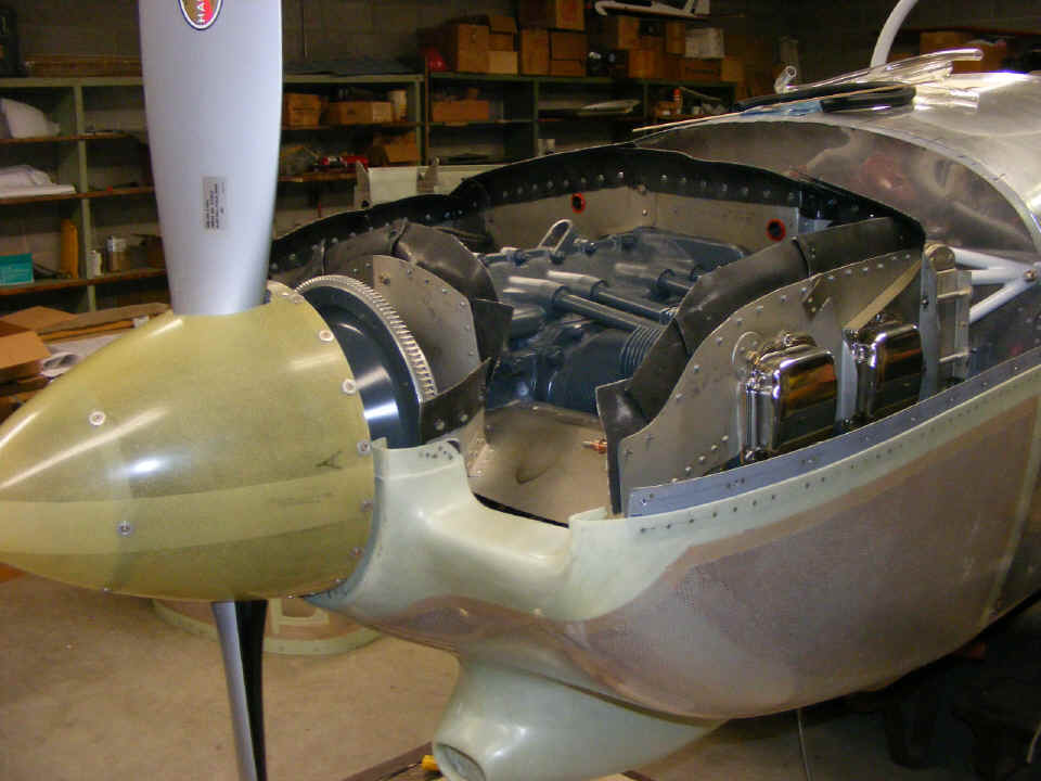
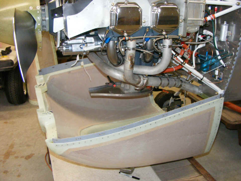
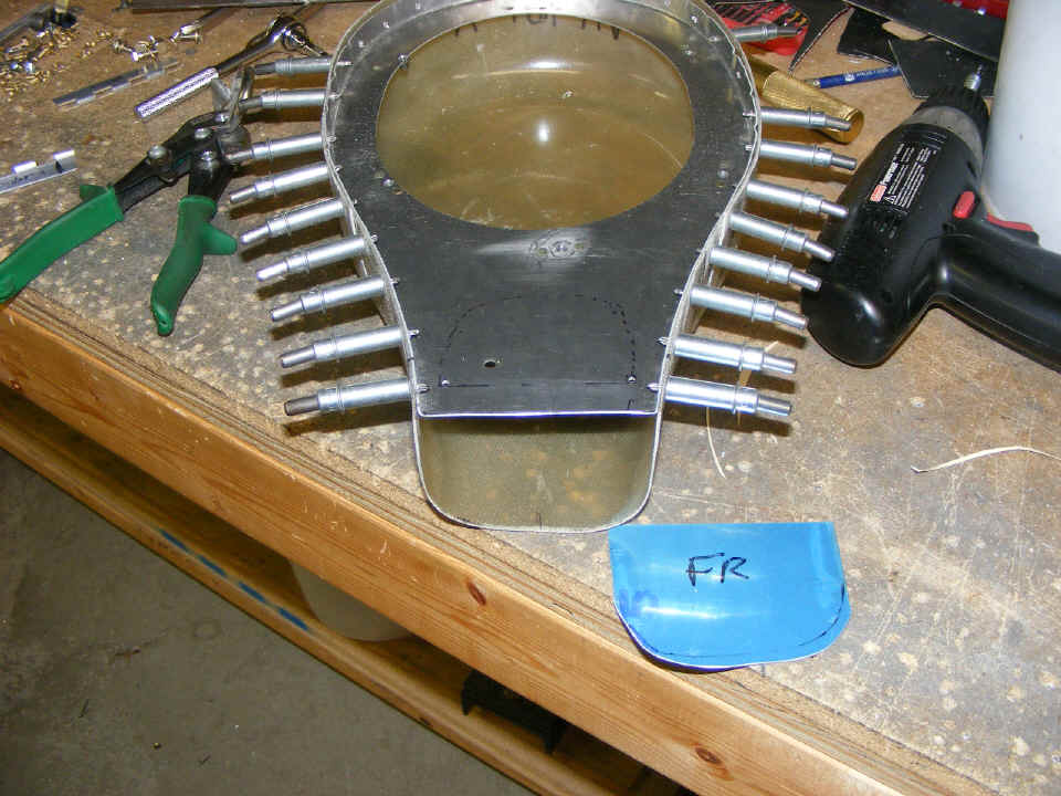
May 7, 2007: The session
tonight focused on the filtered air box alignment. It starts by pointing the metal
plate seen here in alignment with the opening in the lower cowl. We took a
measurement of the distance from the firewall to the front edge of the plate. We
compared the distance from the scoop on the lower cowl to the aft edge of the cowl where
it interfaces to the firewall. The plate gets cut a bit shorter than the length
provided to allow removal and installation of the lower cowl without interference.
The fit of the fiberglass "box" to the length of the shorter metal
plate is next. The plate is then fluted to provide alignment with the shape of the
box as I had done with my RV-9A and O-320 carburetor installation. We drilled one
hole to accept a cleco and taped the rest of the box to the plate to continue the fitting
process with the lower cowl. Since the current design does not have the metal plate
below the air filter as in my airplane, the height of the plate must be accurately set in
relation to the height of the air filter. I helped Wendell to determine where the
filtered air box needs to be to avoid rubbing the lower cowl. You can see the black
circles below that indicate where the carburetor interface plate will be in relation to
the filtered air box.
May 9, 2007: During the next fitting to the
carburetor and the cowl, I noticed a big difference in the vertical alignment of the FAB
to the air scoop in the lower cowl. At that point I realized another difference in
the O-320 and O-360 installations. After carefully reading the instructions for the
FAB again, I noticed a step that was not required when I built my airplane with the O-320.
You will see the results of that discovery later.
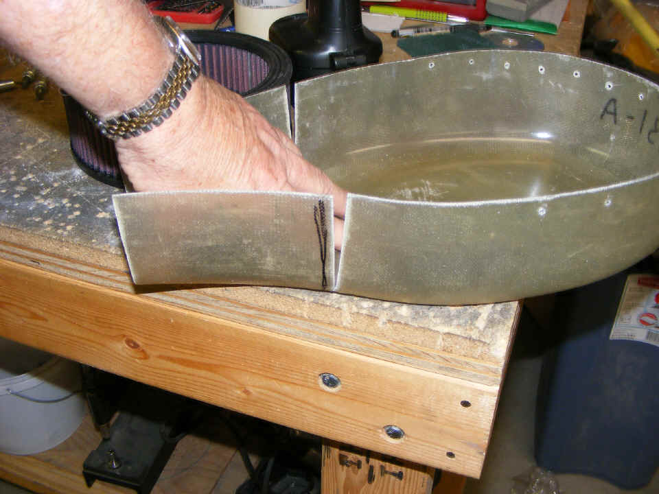
Later is shown below. We had to remove all the flutes in the metal plate
forward of he actual air filter location in the box. That produced the desired
alignment with the top of the air scoop in the lower cowl. These slots cut in the
sides of the fiberglass box allows the front of the box to sag down enough to provide
vertical alignment with the air scoop on the lower cowl. That also brought the top
edge of the box into alignment with the flanges of the upper metal plate. The
resulting gap in the box will be glassed over and filled appropriately with epoxy resin
and 9-ounce glass cloth.
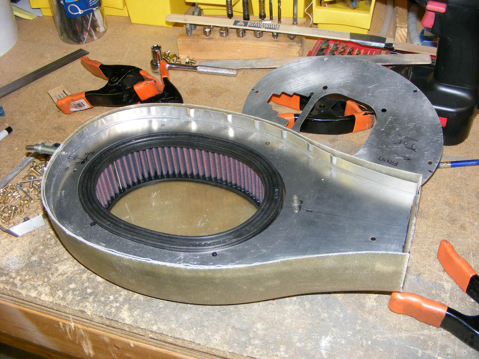
Here is the FAB assembly after drilling all the rivet holes. The
carburetor heat door has also been cut out oversized. I took Wendell into the hangar
to look at how closely my door fits on the front of my FAB.
Wendell wanted me to check his work after sealing the cooling baffle gaps to
the engine with red high-temperature silicone.
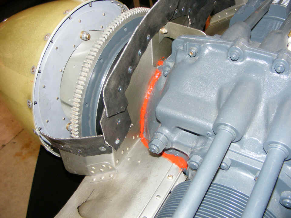
At the end of our session on May 9th, I had pointed out a difference in the fit of the rear baffle plates on the O-360 that was not on my O-320 engine installation. It required the removal of the baffle behind the number three cylinder and bending a tab to fill the extra inch of the cylinder where it meets the baffle plate.
| CLICK for Folks PAGE 52 | Return to Other RV Menu | Return to Main Menu Page. |