Wendell Folks RV-8 Project - Page 47.
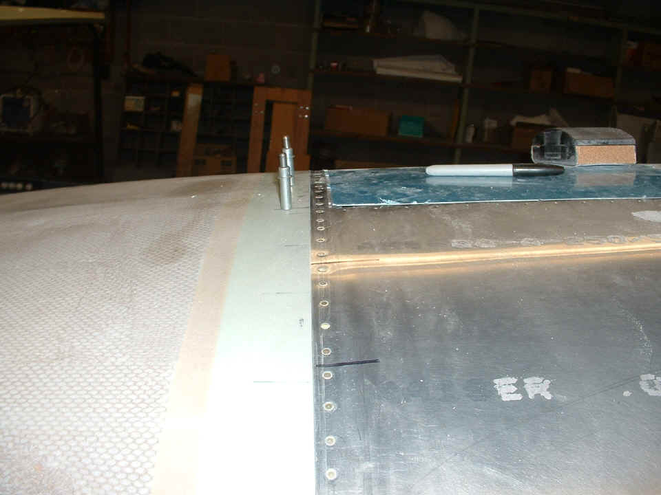
March 15, 2007: I would not allow Wendell to
drill any holes in the cowl or the underlying aluminum plates until I was satisfied a good
fit of the aft edge of the cowl and the fuselage had been achieved. Then and only
then did I permit a single hole to be drilled in each of the metal plates near the center
of the firewall. The clecoes are at the locations of what will become two mounting
screw holes.
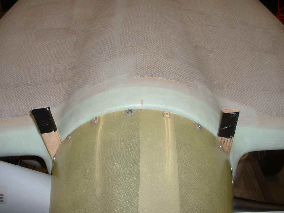
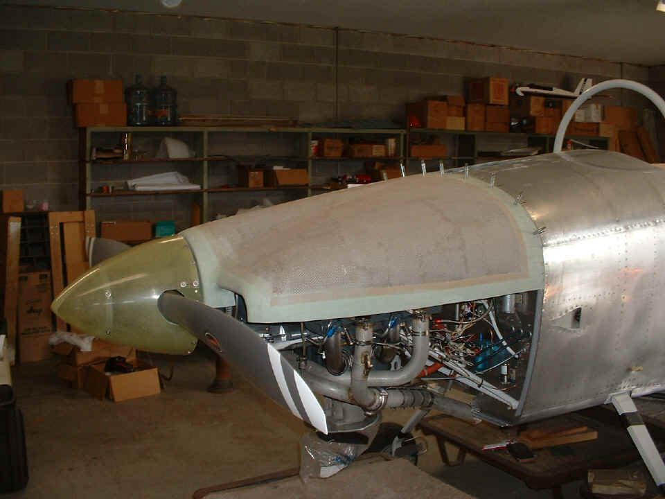
At the front of the cowl, a red centeline was drawn and a matching line was
drilled on the spinner. We had to take great care not to bump the prop to be sure
these two lines could be used to monitor the cowl alignment as the fitting of the cowl
continues. At this point, I pointed out the places where the cowl would continue to
be sanded to insure a good fit with the fuselage.
March 17, 2007: This Saturday session would
see another big milestone in Wendell's RV-8 project. By the end of the session, the
lower cowl fit to the upper cowl would begin. The first step of the final fit of the
cowl was to correct a fit issue with the two aluminum plates that are riveted to the
firewall and the forward top skin of the fuselage. The plates had been turned up
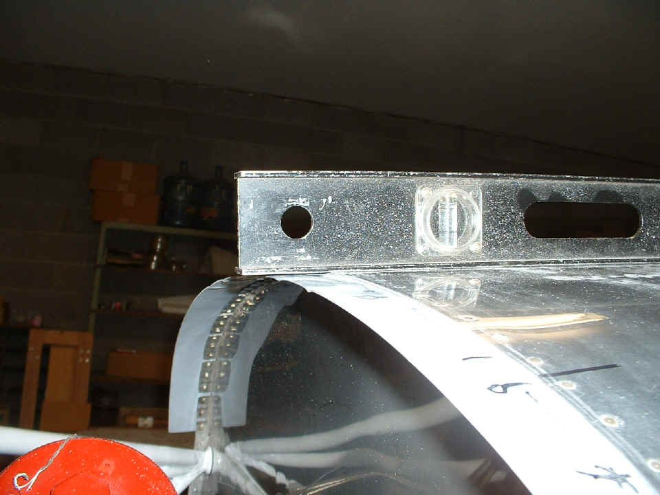
slightly as they approached the center of the firewall. The fluting pliers provided
the correction needed here. The level is used here only as a straight edge beween
the bulkheads at the firewall and the back side of the forward baggage area. The
depth of the flutes were adjusted until the two aluminum plates are parallel to the level.
Only three flutes per plate were required to do the job. Since these plates
were originally flat, the adjustment was made to compensate for the curvature of the upper
firewall where it is riveted to the upper skin of the fuselage.
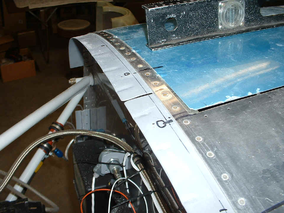
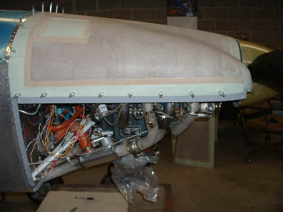
This view from a higher camera angle reveals the location of the flutes to the
position where the screw holes will be drilled. The holes drilled are #40 at the
locations that will be enlarged to accept #8 screws and eventually secure the upper cowl
to the fuselage.
When everything was reviewed a second time, the cowl was finally match-drilled
to the two mounting plates that are already riveted to the upper edge of the firewall and
the forward top skin. With all the clecoes installed, the cowl will now remain in
position for the fit of the lower cowl to the upper cowl and the fuselage. Wendell
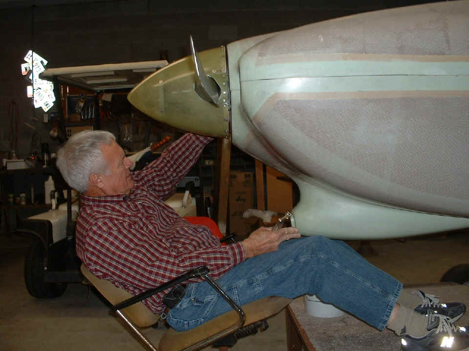
has wooden blocks secured to the top center area of the engine keeping the front edge of
the cowl at the correct height behind the spinner backplate.
The last shop photo of the day was taken after the lower cowl sides had been
cut down to the approximate height of the cowl molded lips on each side of the crankshaft.
There were three of us in the shop during the lower cowl initial fit.
Wendell's friend "Cool" helped us to get the lower cowl overlapped with the
upper cowl sides and the firewall. When the two front corners of the upper and lower
cowl components were lined up, two more #40 holes were drilled near the propeller at the
point where #8 screws will be installed to secure the upper and lower cowl shells
together. With these two clecoes in place, I instructed Wendell to put the lower
cowl in place without any help from us. The purpose was to be sure he could work on
the cowl by himself during the week days ahead when Cool and I will not be available.
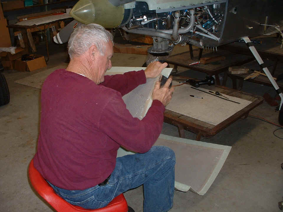
During the new few days, Wendell will be using the sanding block to fit the upper and lower cowl together and to the fuselage skins. We made one final review of the areas that need to be altered and the correct sequence to insure a good fit of the cowl components to the firewall and to each other at the sides and front of the cowl.
It was also during today's session that the aluminum filler plates behind the propeller blades were trimmed slightly to insure clearance from the blades as the pitch is varied in flight. I also had Wendell replace one of the rivets that secure the filler plates to the spinner backplate. The original countersink hole in the plate was not deep enough. As a result there was not sufficient rivet inside the spinner backplate to form a good shop head.
March 18, 2007: I
visited Wendell after returning from Larry Champion's shop earlier this afternoon.
As you can see, the sanding of the edges of the lower cowl continues.
The aluminum plates that will eventally be riveted to the lower cowl have had
screw hole locations drilled in the upper cowl with a #40 drill bit. The plates are
clecoed in position to help with the lower cowl alignment and sanding process.
| CLICK for Folks PAGE 48 | Return to Other RV Menu | Return to Main Menu Page. |