Wendell Folks RV-8 Project - Page 29.
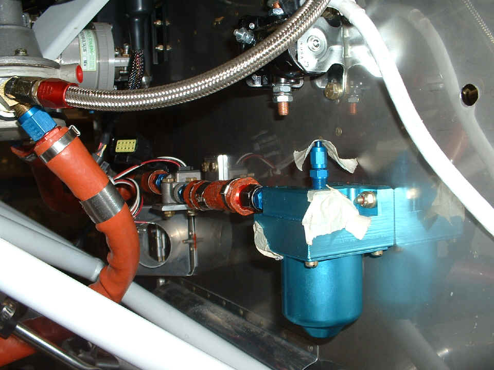
September 27, 2006: The Wednesday evening
session with Wendell shows the mounting bracket for the fuel flow sensor built and
installed between the gascolator and the engine-driven fuel pump. As we neared the
end of the session, it was discovered that one of these bolts will have an Ansel clamp
attached to secure the throttle control cable as it turns from the firewall toward the
carburetor.
The mounting bracket for the tachometer sensor is also made and installed with
a doubler plate on the inside of the stainless steel firewall. We also discussed
using one of the bolts on the Lasar ignition control module with an Ansel clamp to secure
the cables going to the magnetos.
We placed the starter cable in position to check out its routing from the
solenoid to the starter motor. We also did a check of the routing of the throttle
and mixture control cables to check for clearance from other firewall-mounted accessories,
etc.

Wendell had installed the heat muff on the exhaust pipe on the right side of the engine, but I seemed to have forgotten to take a picture of that. The routing of the red air hose from the heat muff to the cabin heater door on the firewall was also examined to verify clearance from the fuel line, and the control cables going to the carburetor. We discussed the other items needed for the work in the next few days, some of which will come from "ACE Aircraft Supply" (Ace Hardware), and some of the real stuff from Aircraft Spruce & Specialty and Van's Aircraft. You can see the letters "M", "T", and "P" are written above the three holes in the firewall to remind us of where the mixture, throttle, and prop controls will come through the firewall.
September 28, 2006:
Thursday evening was another review. Wendell did not get a chance to do much on the
airplane today. We looked at the installation of the strobe power supply location
inside the cabin. Aluminum spacers are needed to allow the bottom skin to be dimpled
for flat-head screws on the belly. The spacers will be countersinked to match the
dimpled skin and serve as doublers to spread the load of the power supply on the bottom
skin. One-inch long #8 screws will be used to secure the spacers with one nut on
each screw, then the power supply will be secured on top of those nuts with nylok nuts.
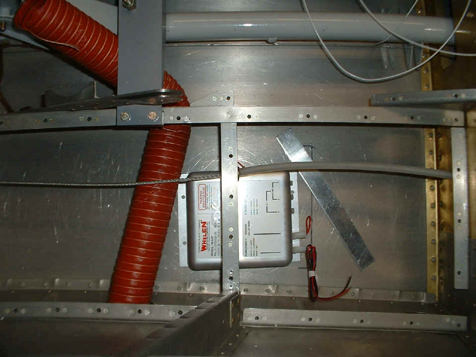
The floor panels on this side of the fuselage are removable to allow access to the
strobe power supply. The area on the right side of the photo is where the rear
passenger right foot well is located. That is why the power supply is under the
floor brace angle. The red scat tube is placed there temporarily to remind us of
where the rear passenger air vent will be located when the wings are put on the airplane.
There will be three shielded cables leaving this power supply when the installation
is completed. One cable going to each wing tip, and one going to the bottom rudder
cap tail light assembly.
We also got out the shopping list for Van's and Aircraft Spruce & Specialty. Saturday will find us online to review those lists and place some online orders to get items that will be needed shortly. We also figured out the best way to route the manifold pressure vacuum lines to the Lasar ignition system and the Grand Rapids Technology engine monitor. SafeAir is sending the correct mounting plate for the altitude hold system. We needed a vertical mounting plate. The unit came with a horizontal mounting plate. We also have to come up with the mount for the elevator servo to the elevator bellcrank behind the battery.
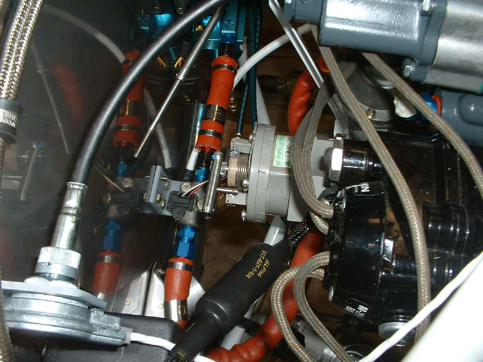
October 2, 2006: I went over to
Wendell's to check on his work with the RV-8. One of the things that needed to be
corrected was on the propeller governor. We called tech support at Van's Aircraft
since the governor was purchased from them. We learned the technique to loosen the
screws on the back of the assembly, then rotate the actuator assembly to the proper angle
to engage the control cable. After that, safety wire was reinstalled. This
photo also gives a good view of the custom-built fuel hose from the gascolator to the fuel
flow sensor.
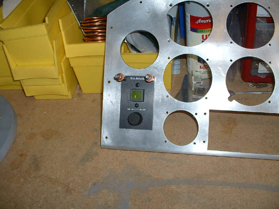
October 5, 2006: The altitude hold system
had arrived from Trio. Wendell had the controls for that unit installed into the
panel in a location that is adjacent to the Trio autopilot wing leveler.
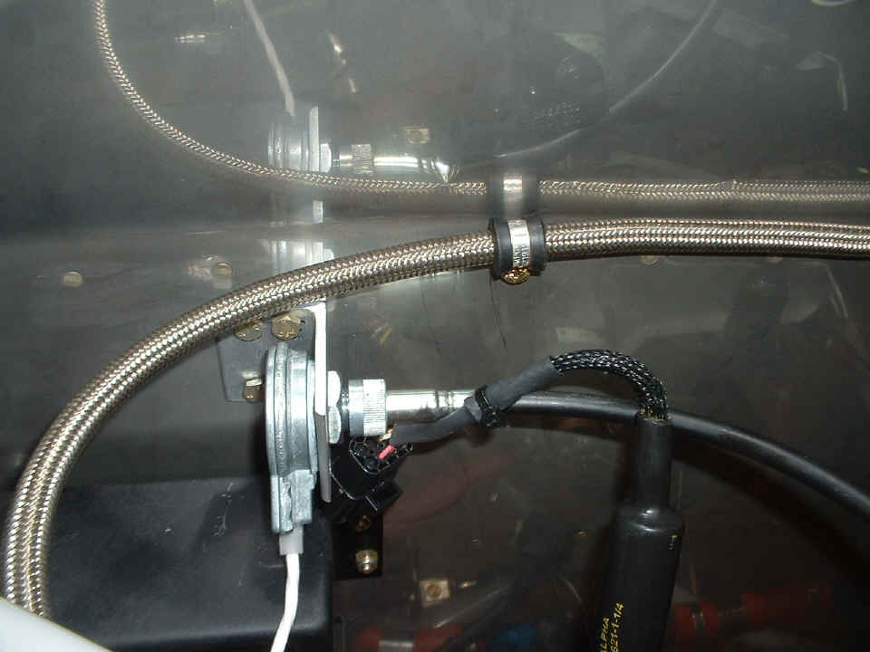
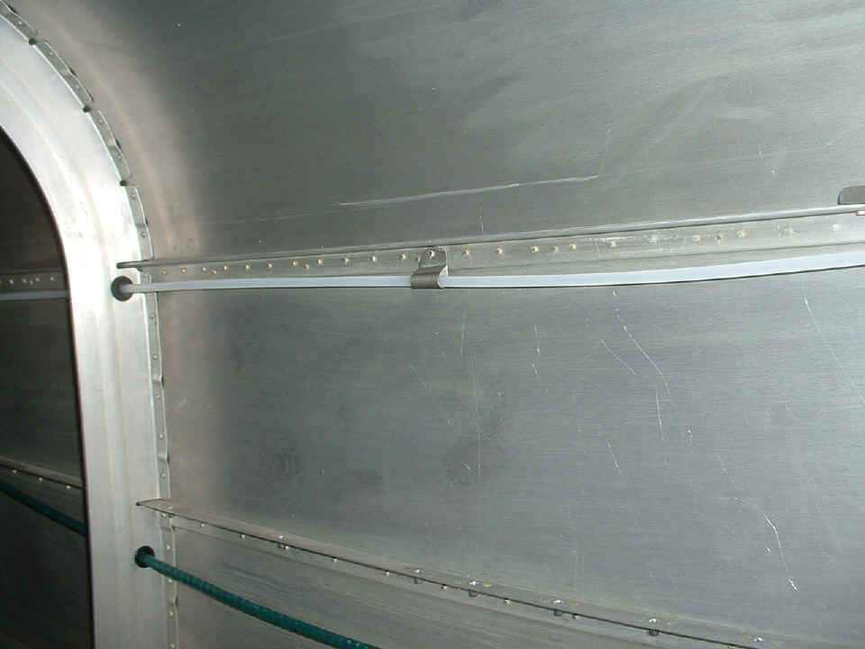
Wendell got inside the aft fuselage with the back-riveting tool in my 2X rivet
gun. I was outside with the bucking bar when he riveted the two clamps to the
longeron, supporting the static air pressure line as shown below.
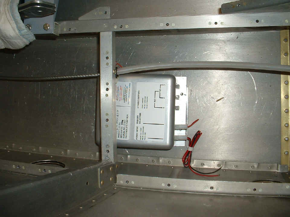
Wendell had already drilled the mounting holes for the strobe light power
supply. I crawled underneath the airplane with my rivet gun to help him dimple the
bottom skin at those hole locations. Here is the view of the power supply mounted on
the bottom skin, just aft of the rear passenger footwell area. There area two
1/8" spacer plates between the power supply and the bottom skin. Those plates
are countersinked to match the dimpled bottom skin. The plates are secured with nuts
on the 1-inch long stainless steel screws. The remainder of the screws stick through
the mounting holes of the power supply and will get #8 nylok nuts installed to secure the
power supply.
| CLICK for Folks PAGE 30 | Return to Other RV Menu | Return to Main Menu Page. |