Wendell Folks RV-8 Project - Page 23.
July 20, 2006: This evening with Wendell was
spent doing some additional training with his 396 and getting the real instrument panel
layout and dimensional checks completed before drilling the first holes in the panel.
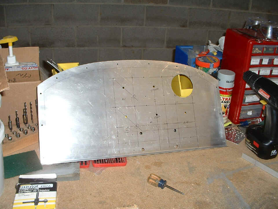
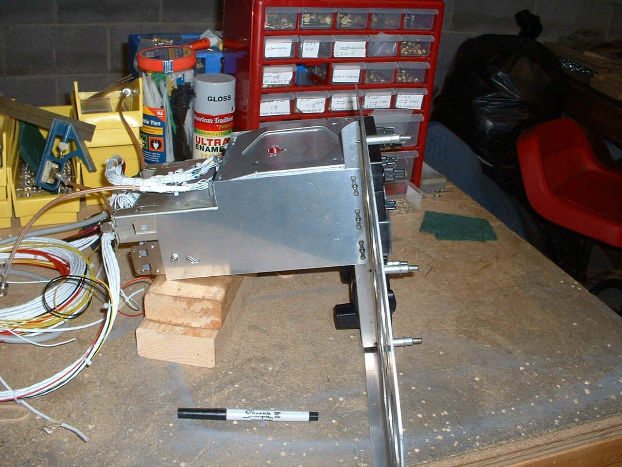
Here is the view from the back side of the panel showing all the screw mount pilot
holes drilled and the large hole for the altimeter has been cut out on the drill press
with the circle cutter. Wendell caught on to the techniques for using the circle
cutter from both sides of the panel to shorten the time to make the cut, and generate less
aluminum chips. He will be using the die grinder and a vixen file to cut out and
finish the square opening for the engine monitor at the bottom center of the panel.
The instructions that I have given this evening will allow Wendell to work at his own pace to finish cutting the large holes for the remainder of the "Six Pack" of flight instruments. In the next session, I will calibrate the cutter for the smaller fuel gauges that will be on each side of the engine monitor at the bottom edge of the panel.
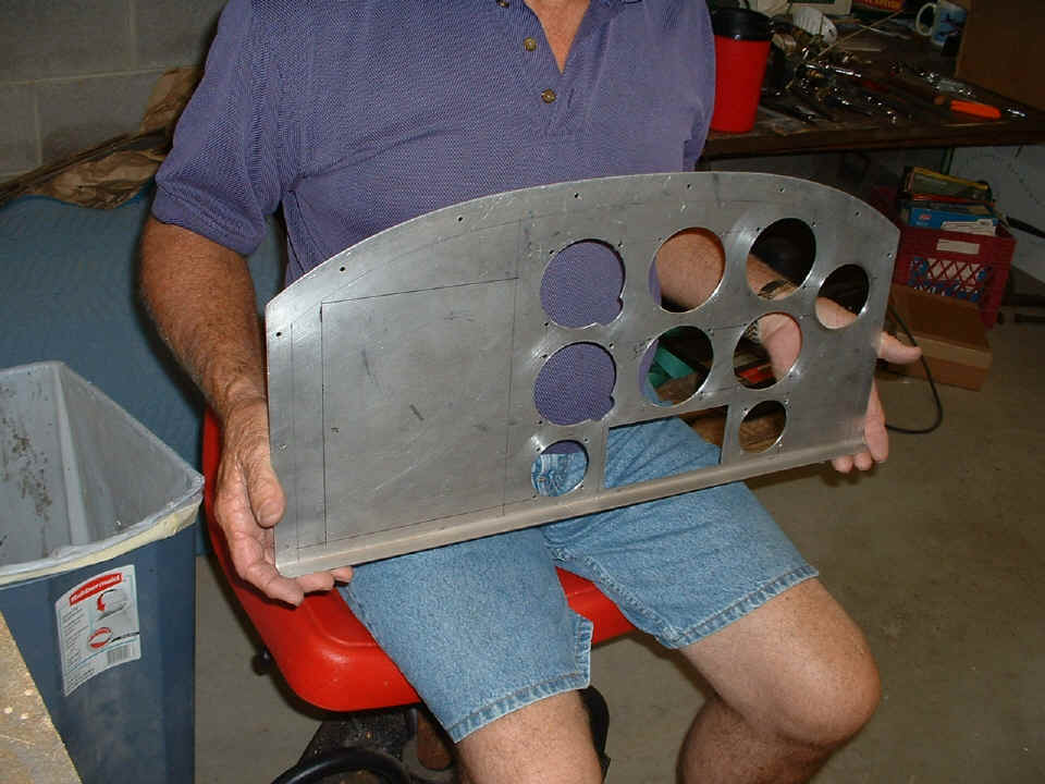
July 22, 2006: Wendell
has been working on the instrument panel to open up all the large instrument holes to the
proper sizes. We discovered that each of the three passive flight instruments are
slightly different sizes. I also reminded Wendell to allow enough clearance for the
powder coating. He waited until I got back to the shop today to cut the smaller
instrument holes for the fuel gauges. He wanted me to check his setting of the
circle cutter before he would make the holes. Here is the view of the back side of
the panel showing the layout lines for the radio stack. There are still some minor
adjustments to be made to the various holes which I have reviewed with Wendell today.
All of that will have to wait until we return from Oshkosh AirVenture 2006.
We depart in the morning (Sunday), probably between 8 and 9 AM Eastern Time.
July 31, 2006: We are
back from Oshkosh and back in our nightly routine of working on the RV-8 project.
Wendell has been finishing up some tasks I had assigned to him in the past few days.
When I got to the shop tonight after 7 PM, I checked out the portion of the panel that had
been removed to accomodate the radio stack and GPS 396 in the Gizmo panel dock. Then
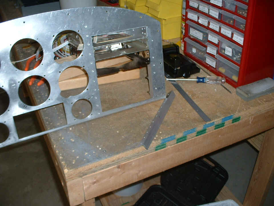
I taught him how to make a radio stack set of "rails" from 3/4" x 3/4"
x 0.062" aluminum angle stock. In this photo below, one rail is clecoed into
position while the second one has been match-drilled and the alignment of the first plate
nut on each side for the radar transponder basket has also been match drilled. The
front face of the panel has been countersinked for the AN3 rivets that will hold the rails
in place and stiffen the panel around the stack. Due to the length of the SL-30
NAV/COM unit, the stack has to be at the top with the GPS at the bottom location.
The reason is the interference of the basket with a cross brace between the gear leg
towers behind the instrument panel. That brace is an important structural member and
will not be disturbed to accomodate the radio equipment in any way. We worked
around it by raising the stack. Wendell wanted to confirm this fit problem one last
time, so we put on the forward top skin with a few clecoes installed the panel, and let
him see it one more time before we made the mounting rails. I had Wendell get into
the pilot seat and hold the stack of three baskets (taped together) in position both high
and low in the panel opening. He saw the problem and agreed with my suggested
solution to place the radio stack.
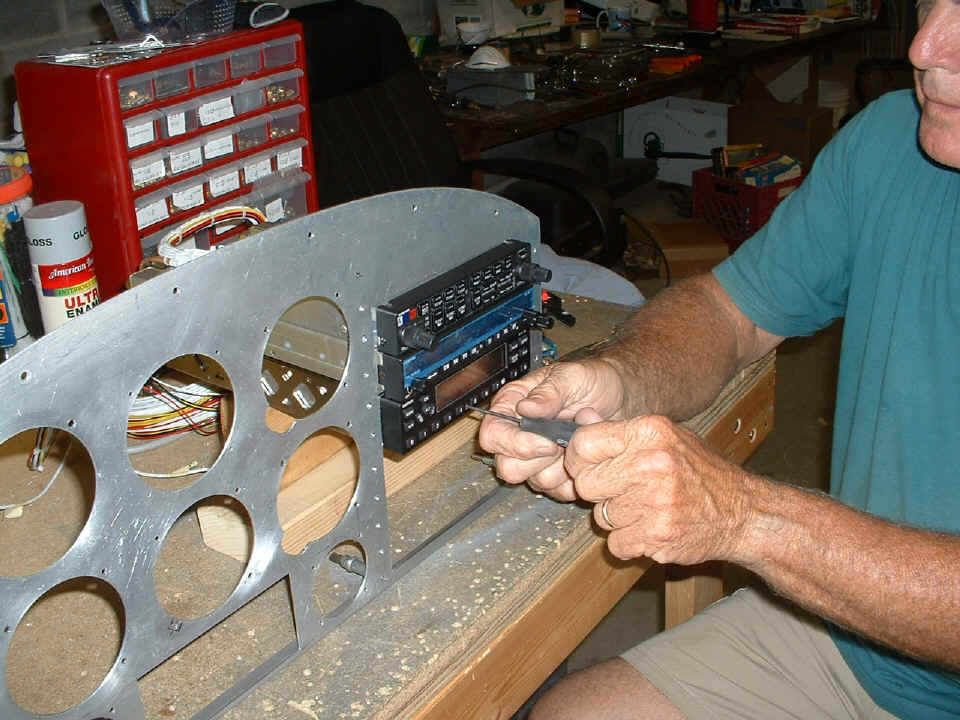
August 1, 2006: Wendell's radio stack needed a
little tweak to the hole placement on the angles. The first set had the three
devices protruding slightly more than we had expected. A second set of mounting
angles were quickly fabricated and new mounting holes for the baskets were drilled to give
the correct alignment of the GMA 340 audio panel, SL-30 NAV/COM, and the GTX-330
transponder. Next comes the installation of the platenuts and the side-mounted shear
plates that will support the baskets from the rear. The AirGizmos GPS panel dock
will be the last thing to be mounted at the bottom of the stack. The space above the
audio panel can be used for alarm lights or an RS-232 data switch going to the Dynon D10A
for data from the SL-30 or the GPS 396. We saw the beta software for a new HSI
screen that will be programmed into the Dynon D10-A when we stopped by their booth at
AirVenture 2006. It is expected to be introduced as a software upgrade in about two
months.
August 2, 2006: Wendell
has fabricated the side plates to support the radio stack. The holes have not been
drilled in the rails to mount the AirGizmos GPS panel docker. The hole in the front
panel for the GI-106 OBS/ILS indicator needs to have a notch cut out it for the bearing
selection knob clearance. You can see where that has been marked in the photo above,
directly above the rectangular engine monitor cutout.
Since Wendell plans to have the panel powder coated, the mounting rails (without
the side panels) will be back-riveted to the front panel before it goes to the paint shop.
We still have a few holes to drill for two RED warning lights and at least two
switches. A third green LED may be installed as a radio transmit indicator to help
avoid a "stuck microphone" condition.
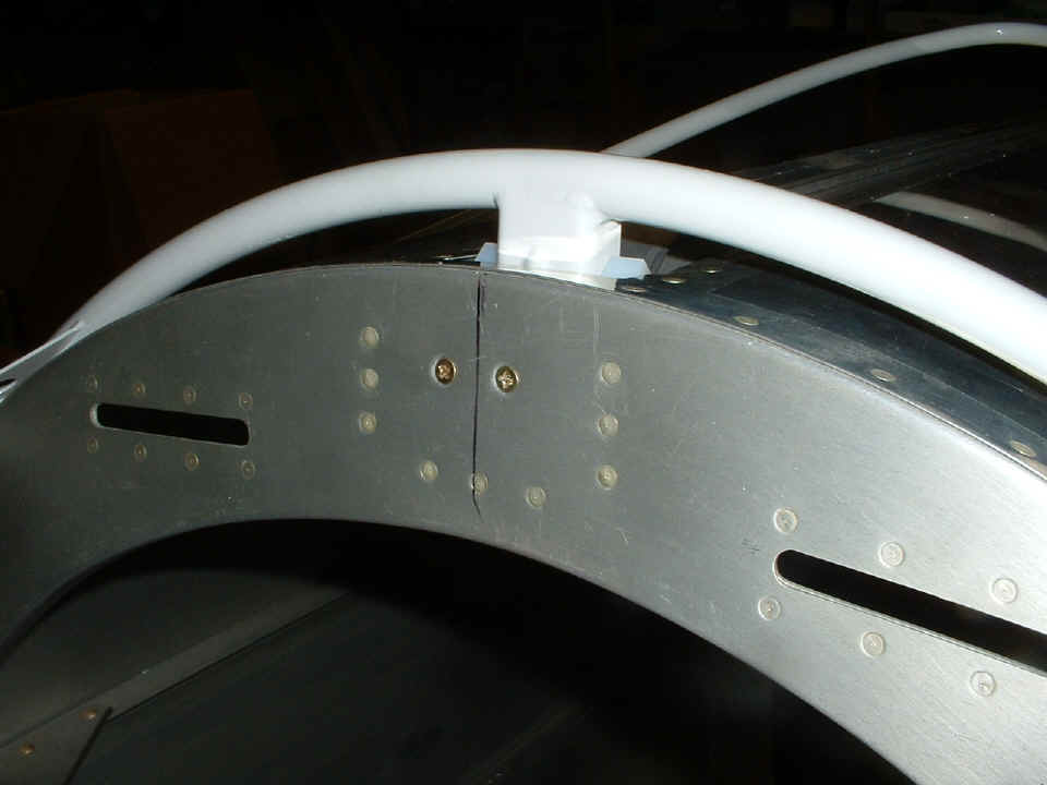
August 3, 2006: I took
some time with Wendell to assist in the alignment of the slider rail on the aft fuselage.
The first time the C661 UHMW block was drilled, it came out "low" and
needed to be replaced and drilled to offer more clearance for the pointed rod that has to
mate with another UHMW block that is mounted against the rear seat bulkhead at the top of
the fuselage. The slider rail has to be centered on the recessed area where the C661
block guides the mating pin into the other UHMW block that is secured to the bulkhead.
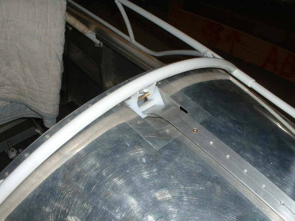
Here is the view from the front side showing the mounting screws that hold the
mating UHMW block to the bulkhead.
Wendell needed to do some additional work on his instrument panel to accomodate the GI-106 OBS/ILS indicator, and one of the radio stack mounting rails needs to be back-riveted better than it came out on his first try.
August 8, 2006: I had a visit with Wendell when I got back to the hangar after my business travels yesterday. He had finished the double blind riveting of the slider rail seen two photos above this entry. He called during lunch today to tell me his Hartzell propeller arrived today.
| CLICK for Folks PAGE 24 | Return to Other RV Menu | Return to Main Menu Page. |