March 2018 Melbourne Air Show · · PAGE 436.
March 25, 2018:
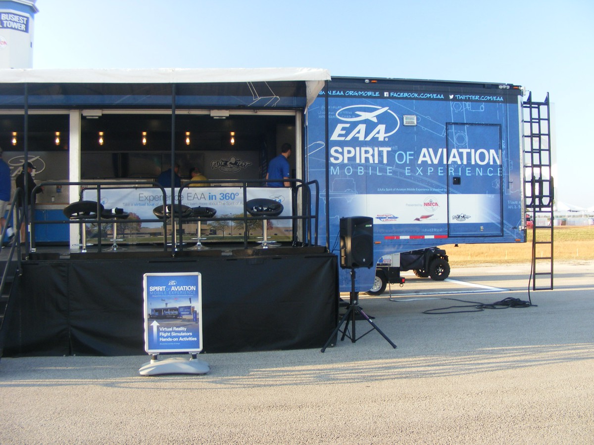
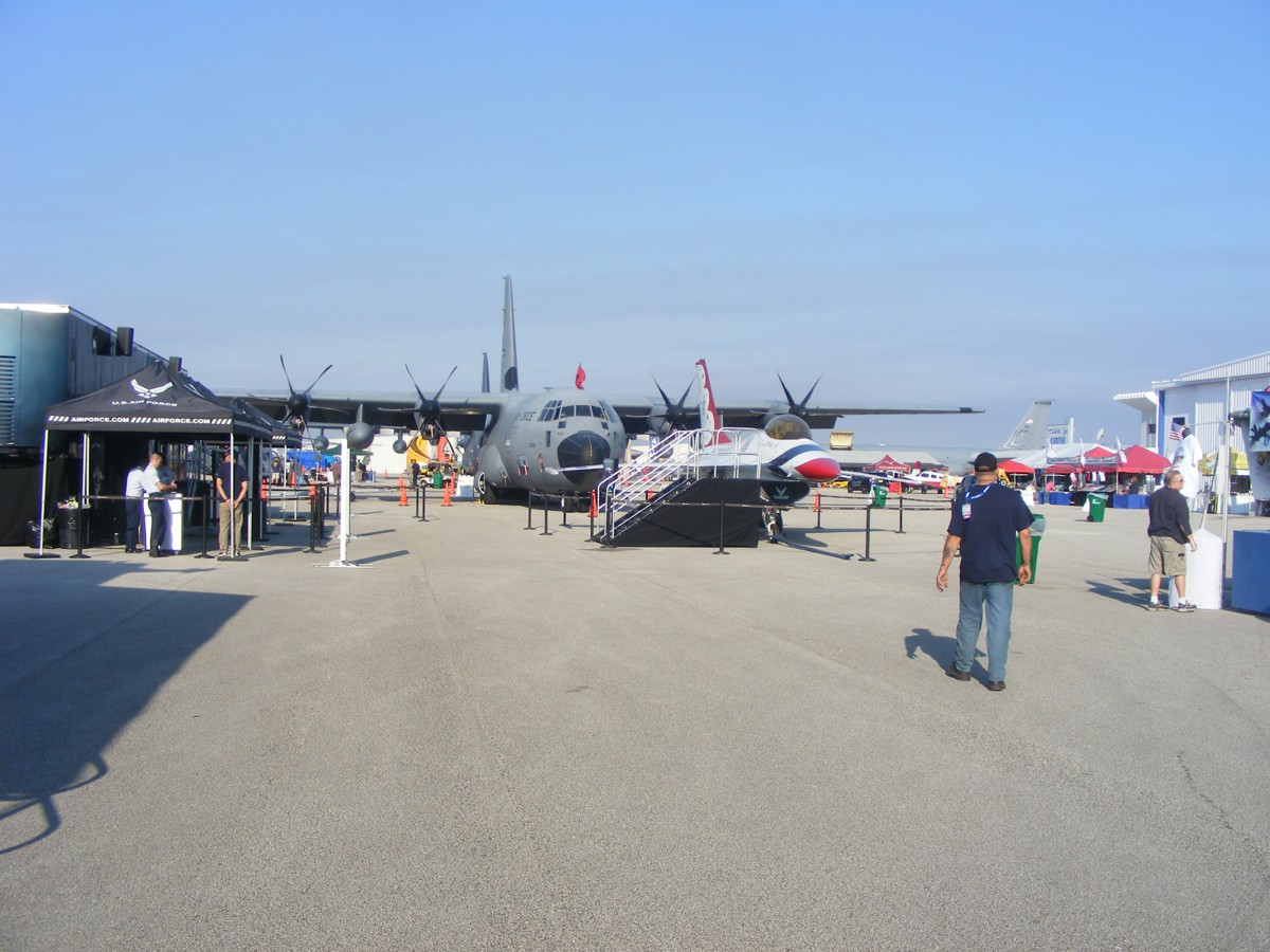
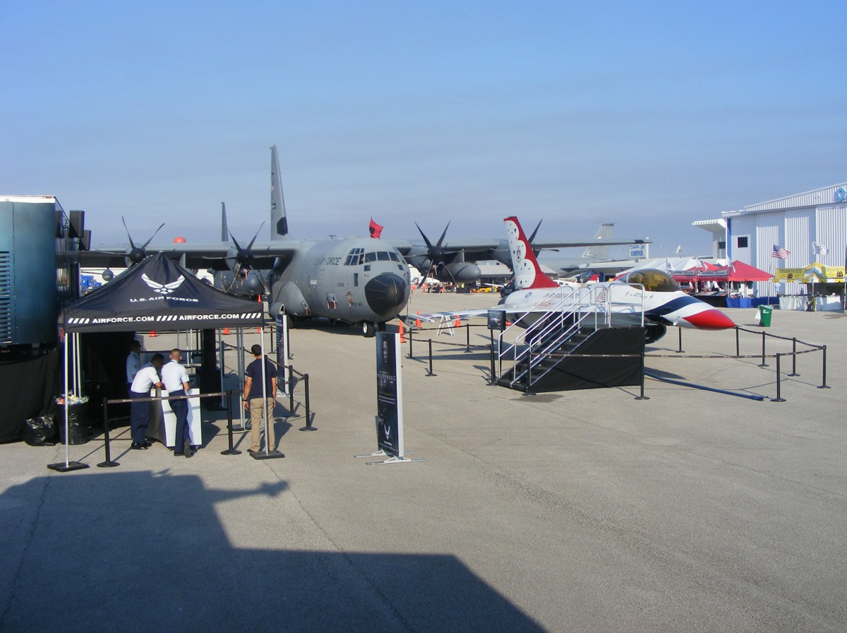
This Sunday was the second day of the Melbourne Air Show with the US Air Force
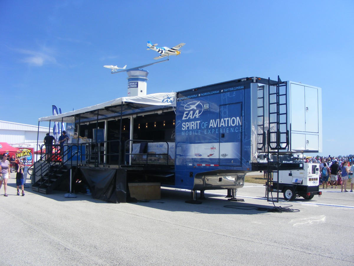
Thunderbirds as the main attraction. I was busy as a volunteer for the
Experimental Aircraft Association mobile exhibit.

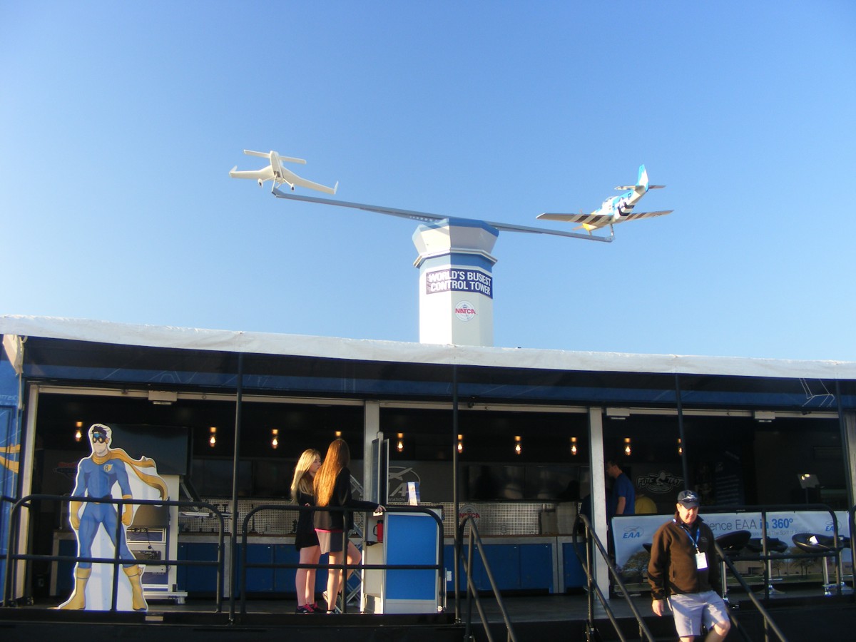
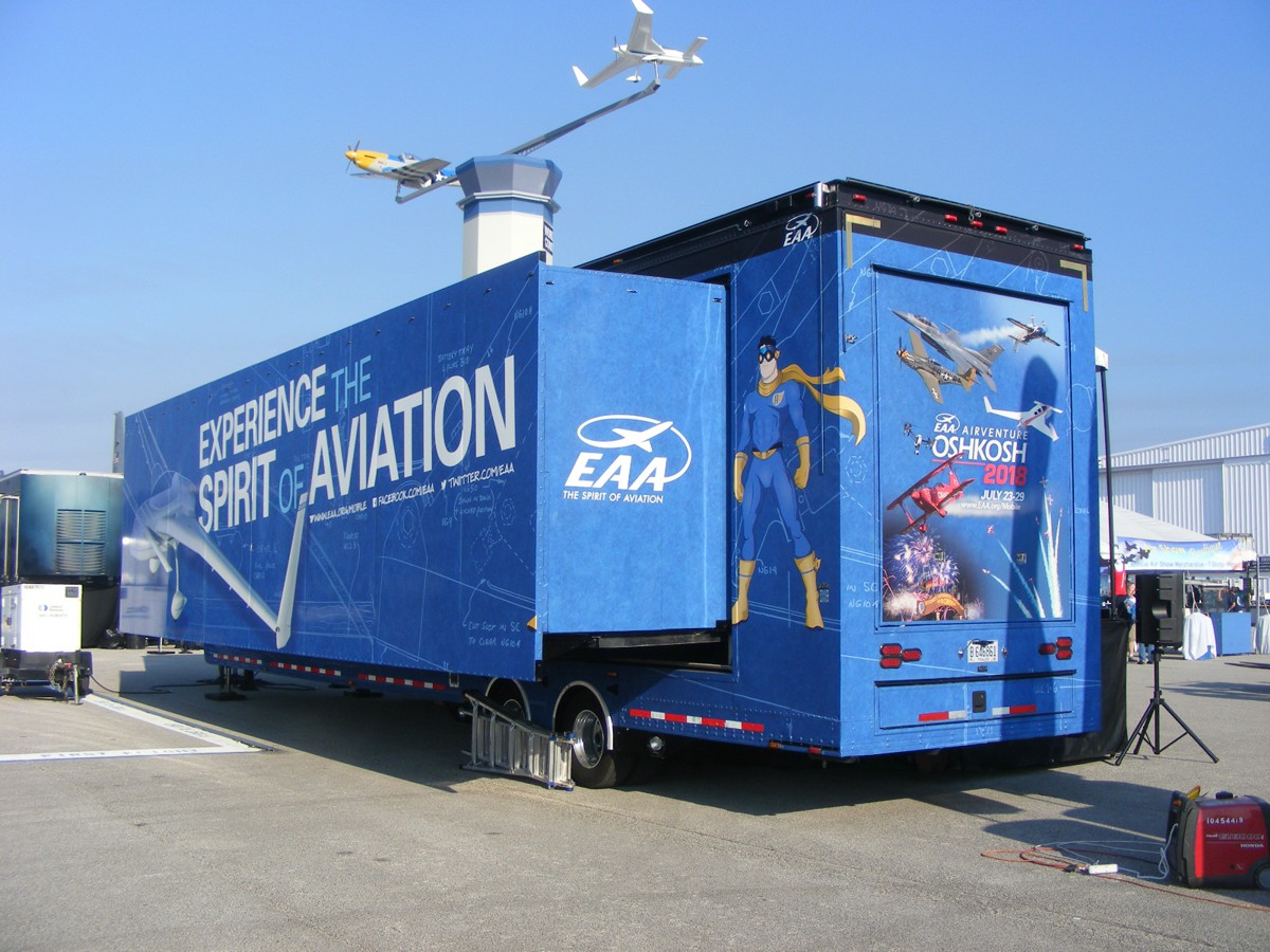
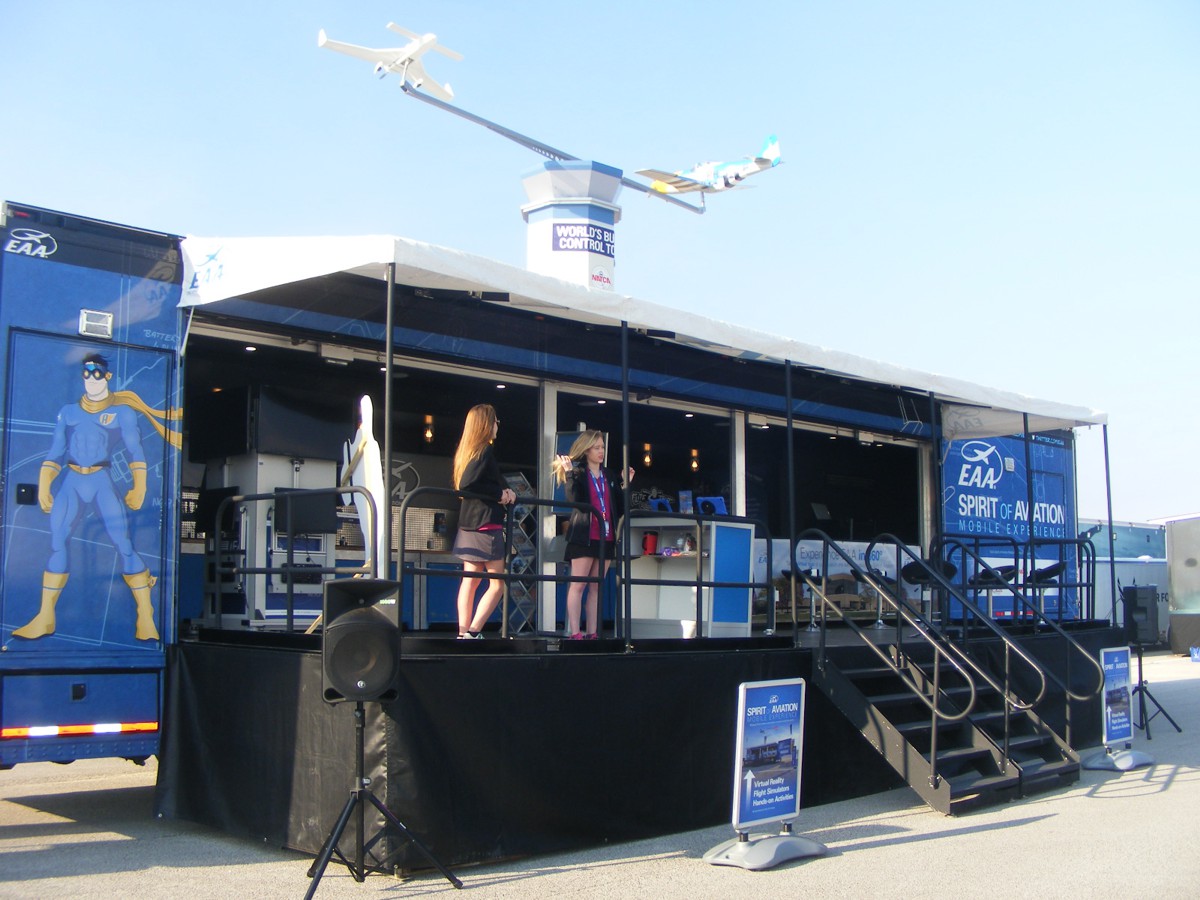
The booth next door was the US Air Force.
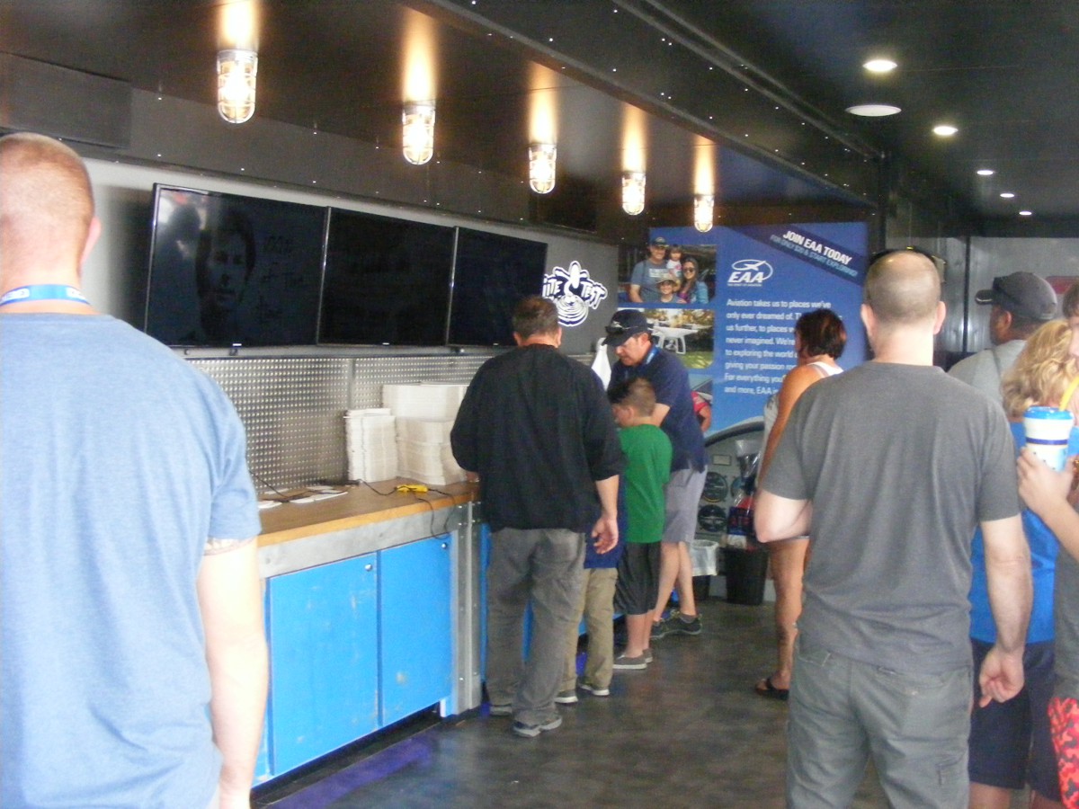
I spent the day with children from age 4 to 14 building paper laminated
over foam gliders with a hot glue gun. The fuselage had only three parts
that were glued together before inserting the wing.
There were sonic booms later in the day that shook our exhibit as they did
everything else in the exhibit area. I paused for one more photo as I
started leaving. I did get a tour of a refurbished Boeing KC-135 air
tanker before leaving the area.
March 31, 2018 - More work on the Annual Inspection.
March 31, 2018: This Saturday was about
checking the brake pads, main wheel bearings, and setting the tire pressure at
35 PSI. The nose wheel was serviced a few months back when I used the
electric winch to get the nose wheel in the air. That day was also about
setting the tension on the fork.
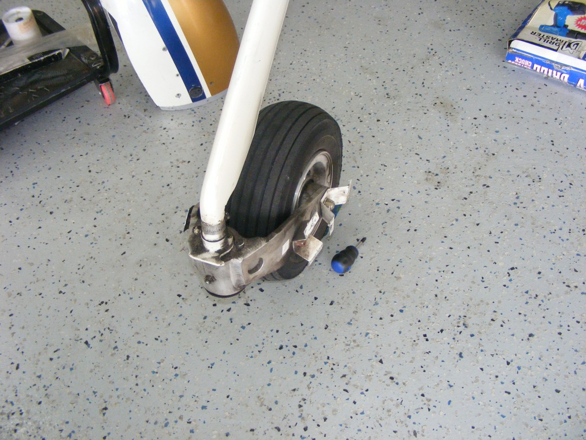
The main landing gear tires will be replaced soon.
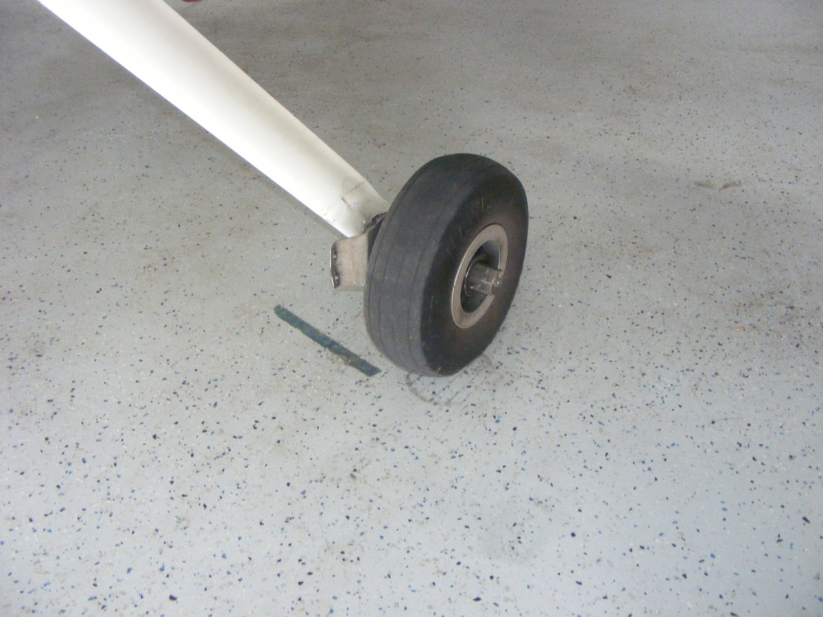
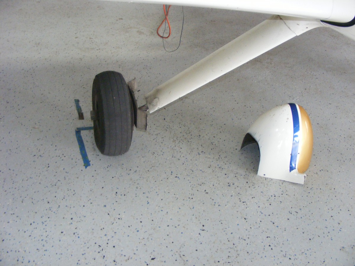
This hydraulic jack under the wing tie-down was how I lifted the main
landing gear legs off the hangar floor to check the wheel bearings. I
could see the brake pad thickness when I removed the wheel fairings to add air
to the tires. That "HOLE" in the wing at the upper right corner
of this photo is the plexiglass window in the leading edge of the wing with a
landing light inside the wing.
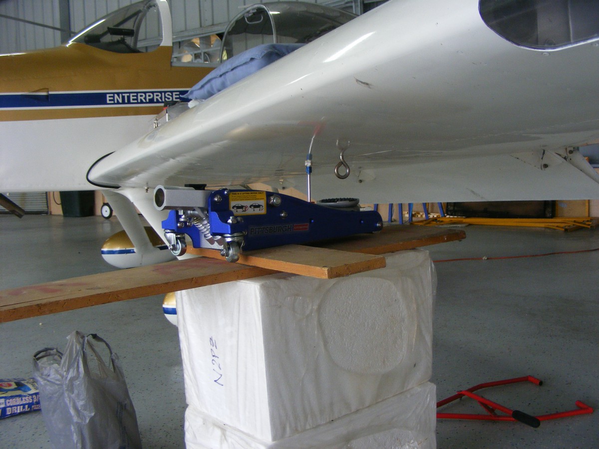
These foam blocks I have used in the past when doing this work at Wendell's hangar in Georgia. The foam blocks are from Tractor Supply stores. They are used to stack farm trailers for shipment to their stores. After that, the foam blocks are discarded.
April 14, 2018:
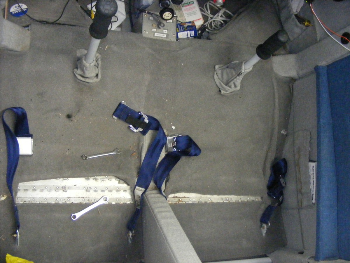
This Saturday was more inspection to confirm the control sticks are still
properly connected to each other and the aileron push rods going out to the
bellcrank in both of the wings. Removing the seat backs and cushions was
the first step to access the control linkages. The seat belts and the
"carpet" under the cushions were also removed before I could access
the panels over the control linkages.
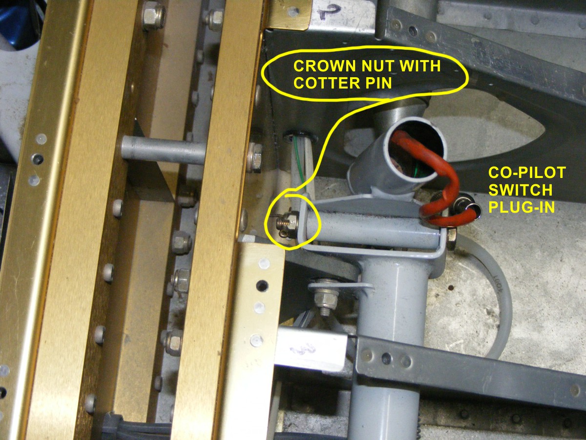
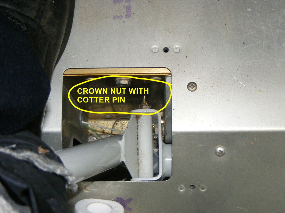
The crown nut and cotter pin holds the bolt for lateral movement of the
control stick. This one is the removable passenger stick
location. There is a push button on the stick for the communications radio
push-to-talk function. That GREEN wire is that PTT connection to the
radio.
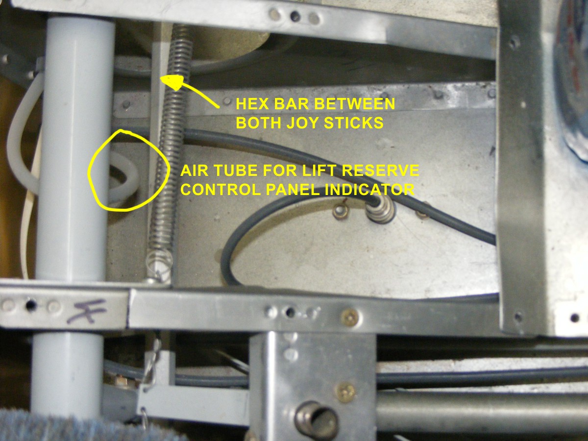
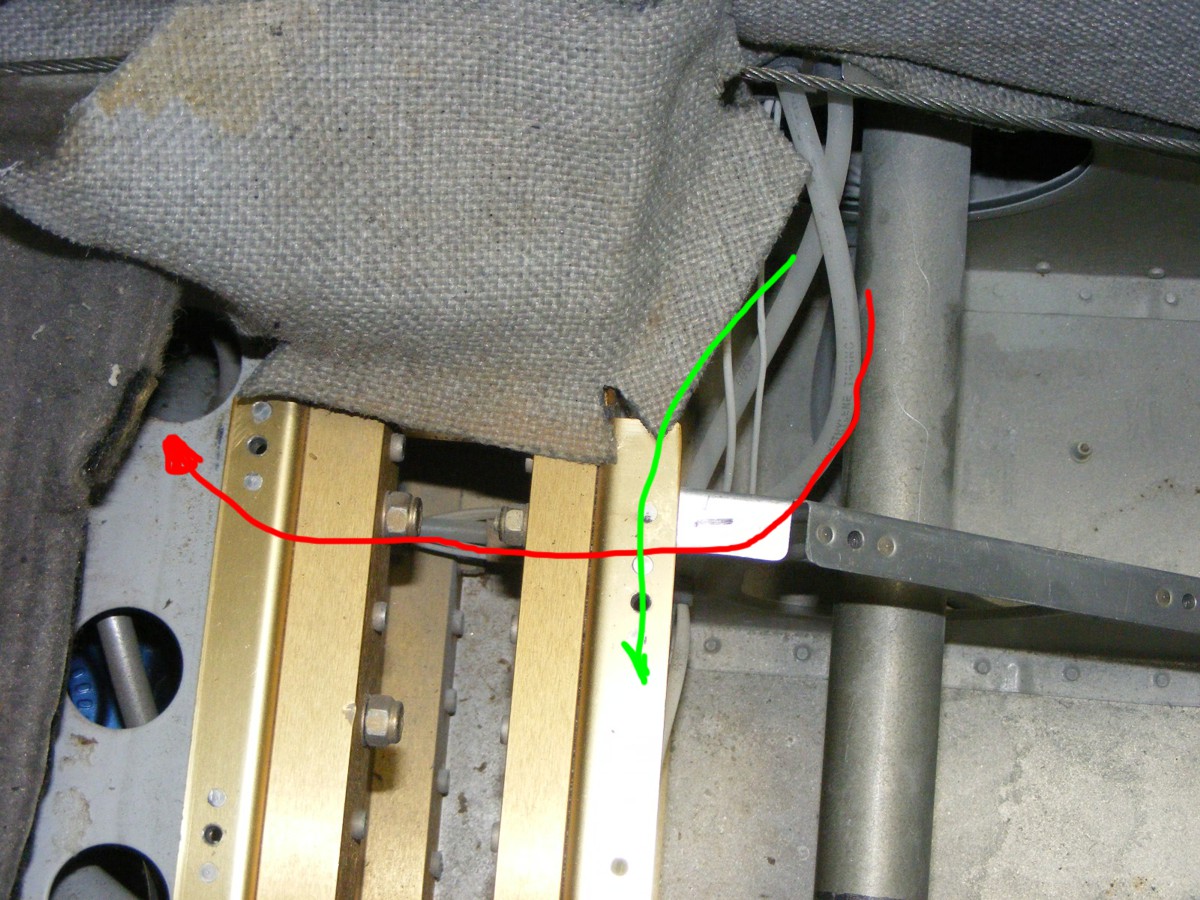
The movement of the control sticks to the FULL UP position during ground
taxi operations has been rubbing one of the two PVC tubes that go to the lift
reserve indicator in the instrument panel. There was no sign of wear, but
I relocated the curl in that tube with the slack in the extra tubing in this
area. The black coaxial cable and BNC connector connect to the radar
transponder and the antenna on the belly pan below the seats. I will be
revisiting this area to install an ADS-B output transmitter module before
January 2020.
The wing spar carry through members have both wings plugged in and secured
with eight bolts to attach each wing. You can see all this stuff in the
first two photos on PAGE 19
when I was building the fuselage. The wing bolts were installed on PAGE
122 via this web link on May 4, 2005.
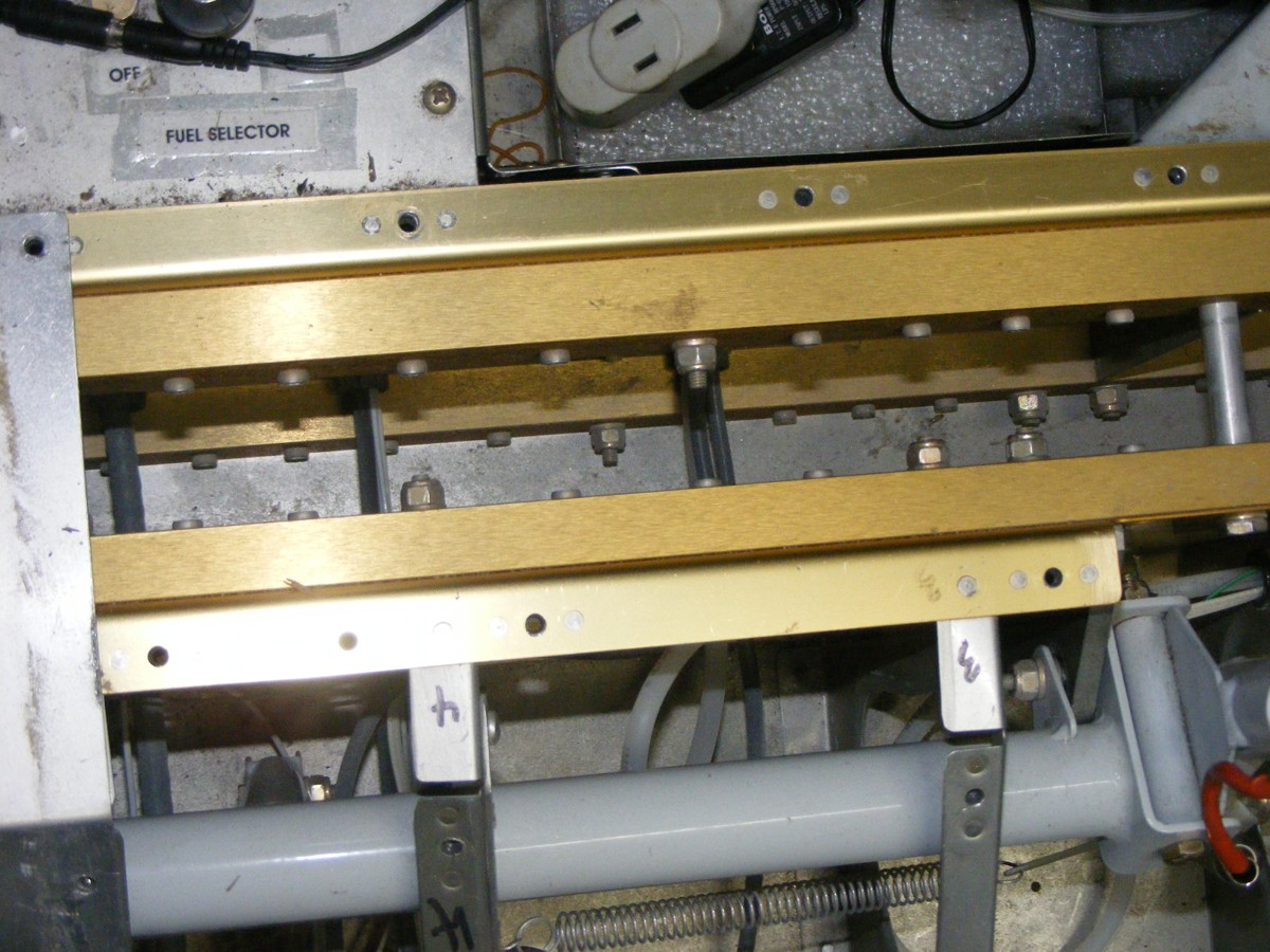
The photo above shows both air tubes for the lift reserve indicator being
routed through this area. The routing of the two air tubes are shown in
this next photo.
Here is the pilot control stick with the important bolt also secured with
the slack that allows free movement of the stick.
April 18, 2018: The new photos above from April 14 were posted today. I ordered new Miami and Jacksonville sectional charts yesterday from Aircraft Spruce.
April 28, 2018: Saturday
morning and my BFR flight today with a local CFI from Rockledge. It was
his first ride in an experimental amateur-built aircraft. I opened the
cowl to point out the features of my ECI O-320 Lycoming-style experimental
engine built by Penn Yan Aero. I explained the shaping of the longerons
from the firewall to the tail, pitot / static ports, and the lift reserve
indicator probe and passive gauge in the instrument panel. After lunch we
took a one-hour flight as seen below.
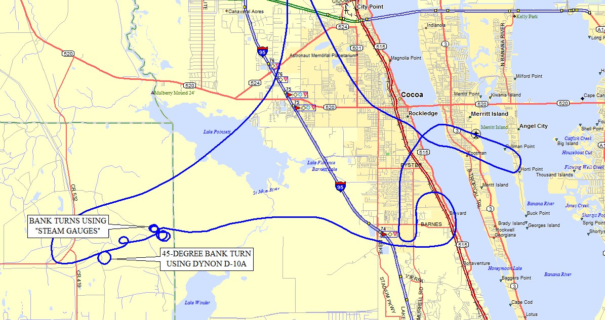
The CFI had not seen a Dynon D-10A before today's flight. I was trying to use the vertical speed gauge to maintain altitude in the 45-degree banked turns with not much luck. He pointed out that if I put the "airplane circle" of the D-10A just above the horizon line as I banked to 45 degrees, I should find it easier as my eyes would stay on that screen. Take notice of the near perfect circle. These maneuvers were performed at 2,500 MSL and 120 MPH indicated air speed. The power-on stalls were easy at 60 MPH.
Winds at pattern altitude of 1,000 MSL were around 15 MPH at all three airports: Rockledge, Titusville Executive, and Merritt Island. Being at the river, the winds at Merritt Island were from the north at ground level making the cross wind landing a good demonstration for a touch and go landing. The crab angle was about 20 degrees to the right down to 10 feet when I pushed the rudder pedal and cross controlled the ailerons for a good touch down. The wind at takeoff from Rockledge was directly down the runway from the north. Upon return the 15 MPH wind at 1,000 feet was aligned with the runway from the north. On the approach, the wind changed from 15 to 6 MPH from the East and dropped to near zero in ground effect before landing.
The Hobbs meter added 1.0 hours today.
| CLICK HERE for PAGE 437 | Return to MAIN MENU |