Airport Assembly - Page 130.
May 26, 2005: Today was an interesting day.
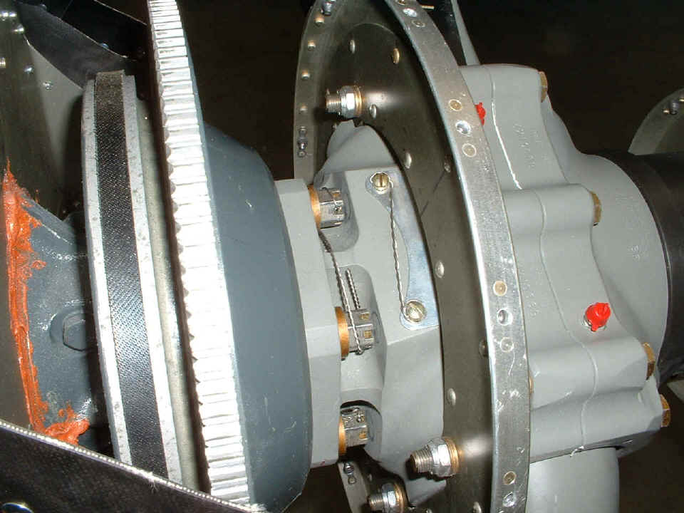
Much of what I had planned from yesterday's postings came to pass. The prop
safety wire was put on correctly as you can see from these two photos. My wires are
the ones on the big bolts. Hartzell did the ones on the screws.
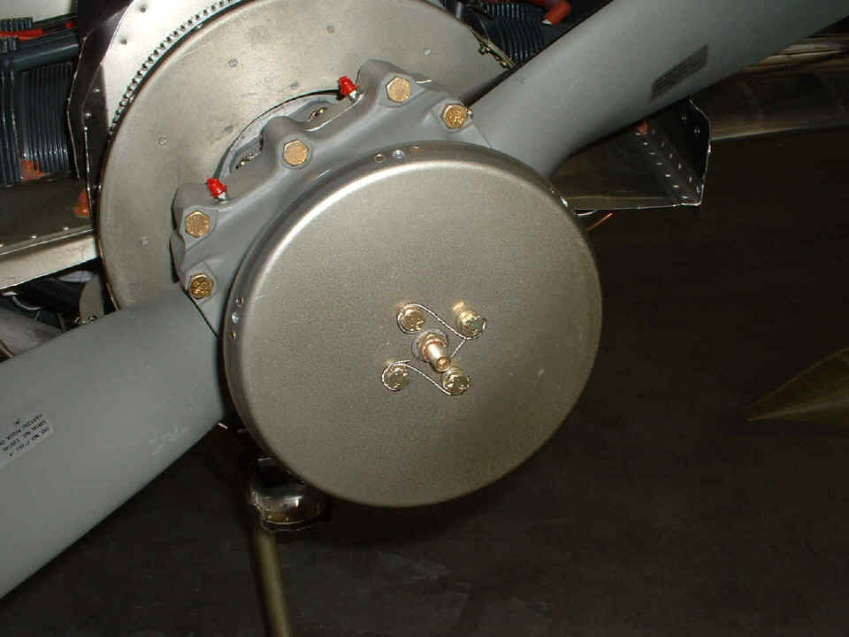
I also put these bolts on the front prop spinner bulkhead and put in the safety
wire. Rich Nadig showed up, inspected these installations, and then things got very
busy. And that is why I did not take any more pictures today.
What classic photos did we miss? How about the airplane up on the scales! I was busy working with Rich to put in 25 pounds of ballast to represent the interior and seats, and all the covers and bulkhead panels inside the cabin. When it was all over and the scales were put away, it dawned on me that I had not taken a single picture of the process! Don't worry, I get to do all that stuff again when the airplane gets painted.
Here are the facts of the day:
1. The engine oil was put in and the dip stick calibrated at the 6-quart
level IN THE CRANK CASE.
2. I ran the starter with the aviation spark plugs removed to circulate the
oil at 50 PSI throughout the engine and oil filter.
3. I discovered just how much the oil level in the crank case is reduced when
the oil filter fills up.
4. I poured about a gallon of 100LL fuel in each tank and pumped it out to
leave only unusable fuel in the tanks.
5. I discovered a loose fuel line fitting on the hose leaving the gascolator
during the operation of the electric fuel pump.
6. The Hobb's hour meter ticked over from 9999.9 to 0000.0 hours when the
engine starter run/oil circulation tests were completed.
7. The total weight of the unpainted airplane today is
1,150 pounds.
I did some preliminary calculations of weight and balance with worst case loading and they are within the forward and aft limits from the datum reference point called out in Van's sample calculations from the manual. I will be creating a spread sheet with all the possibilities from Van's work sheet for my airplane. The extra weight from the constant speed prop definitely is an issue that will allow more weight in the baggage area and still keep the CG within the range of 7.95" and 14.84" aft of the wing leading edge. I have to research an oxygen system and add that to my total weight of the airplane and decide where it will be mounted to keep the weight and balance in that range. My goal is to verify that the airplane will be within the CG limits at approximately 1,900 pounds gross weight. This is 150 pounds over the target weight that Van's recommends, but certainly within the capabilities of the airframe. When I was at the 2004 Saturday night Van's banquet at OSH last year, John Johanson told us about how he rebuilt his world spanning RV-4 to have a "wet wing" before his Antarctic adventure. The gross weight of his airplane at take off with 1000 liters of fuel (264 US gallons) was approximately 3000 pounds.
Van's sample weight and balance solutions use 175 pounds for the weight of an "average pilot". Since I am a big guy at 230 pounds, I looked at the numbers on that side of the tally sheet first. The actual numbers from my GROSS WEIGHT calculations were 1,876 pounds with a total moment of 155,519.9. This gives a CG at 82.8" aft of the datum line. The Van's design limits aft of datum range from 77.95" to 84.84" aft of the datum line reference. The example showing five gallons of fuel remaining after a flight at gross weight provides an answer of 1,690 pounds and the CG at 83.5" aft of the datum line. When you consider that the CG range allowed is only 6.89 inches, my worst case AFT CG is 5.55 inches from the forward limit or just over 80% of the allowable distance. With full fuel at takeoff, the limit would be at the 70% range.
The first engine start should be in the next working session at the airport. Before that happens, I have to complete and mail my paperwork to the AB-DAR that will be inspecting the airplane on June 8th. Taxi testing is authorized, but no flights until I get that airworthiness certificate and get my insurance upgraded to flying coverage.
May 27, 2005: No engine
start today. I had to finish my spreadsheet and paper work on weight and balance and
get the whole package of documents off to Birmingham, Alabama. By the time I got to
the airport after lunch, it was nearly 3 PM. I decided I would not start the engine
by myself. I would like to have someone standing by to observe during the first
start. I missed that fuel leak when the unusable fuel was to be determined, and I
don't want a similar occurrence during the first engine run while I am busy in the cockpit.
I do have pictures for you today from the 4.6 hours worked on the airplane.
Here is the first view of the spinner with the correct flat head screws and
countersunk washers in the thick fiberglass spinner material.
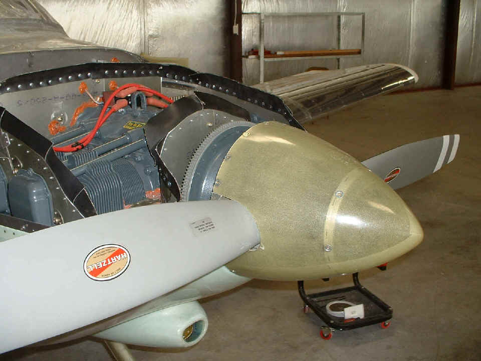
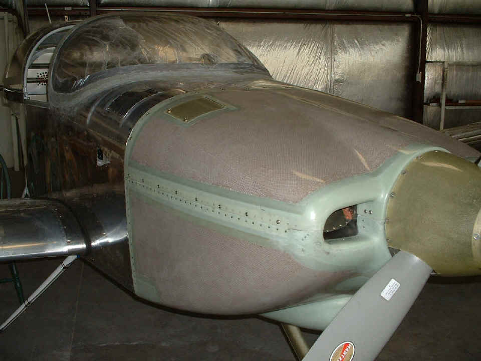
Next is the cowl fully buttoned up and ready for engine start. I charged
the battery last night and it is topped off!
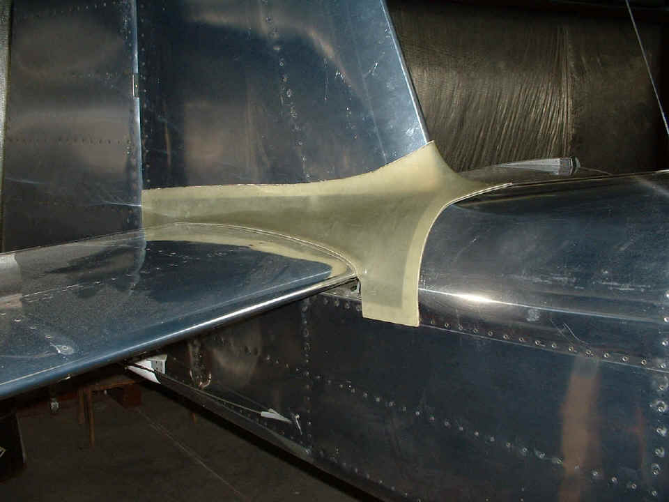
Then I spent some time on the F994B fiberglass fairing for the empennage.
I trimmed off the excess glass to clear the elevator control arms and to remove the
excess material around certain edges as needed. I need to fit the two aluminum
plates that go under the horizontal stabilizer before I can drill the holes in the glass
for the various mounting screws that will secure it to the metal parts.
Here is the underside of the RIGHT wing at the aileron inspection plate.
The lift reserve indicator probe is now connected and ready for action. I set up my
mirror on the bulkhead behind the passenger seat location in order to see the LRI panel
gauge when I am sitting in front of the probe with an air hose in my hand. Using
low pressure, I put the air nozzle about a foot away from the probe and used my left hand
on the probe to alternately cover the two holes in the probe while blowing air across them
and observed the movement of the needle on the LRI gauge. Of course the hoses were
connected backward (50/50 chance). The correct way to connect them is "black in
the back". That refers to the one hose with the black tape on it connected to
the rear fitting on the probe. The next time I take the instrument panel out, I have
to confirm which of the two fittings on the gauge has the black tape-marked tubing on it.
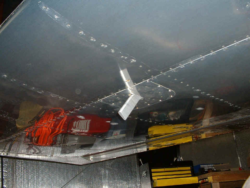
I just want to be sure you know exactly which part of the right wing you are
seeing here. This is the underside with the aileron at the back edge of the wing
reflecting the yellow drawers of the tool chest. You can see the outboard aileron
hinge and the white gel coating of the fiberglass wing tip at the left side of the photo.
The wing spar is just in front of the access plate that has the probe mounted on
it.
And the last photo of the day is the instrument panel back in position and all
items present or accounted for. Garmin sent back a replacement audio panel to me
this morning. DHL delivered it while I was working on my weight and balance
spreadsheet. This one works properly on the ICS inhibit, and the speaker works on
this one without any oscillating pulses the way the other one did. It was not my
wiring that was giving me grief before, it was a bad unit. It seems that I may not
need that resistive audio impedance matching network after all. I will let you know
when I get the GPS audio out reconnected to the audio alert input of the GMA 340 audio
panel and test it.
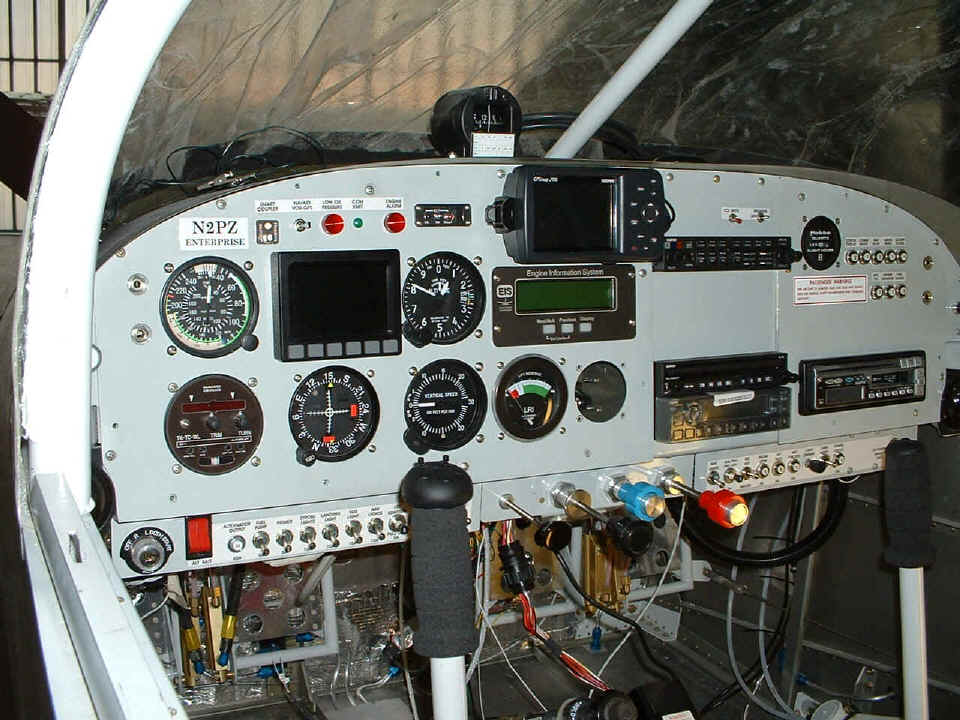
And of course, I want to account for the empty hole in the panel where the fuel
gauge goes. Look carefully at the bottom center edge of the photo and you will see
the elevator trim knob, and just to right of it is a black box with a white label on it.
That is the gauge hanging by its wires and the big black round connector visible
under the carb heat knob that is pulled out. The fuel gauge will live out of the
panel until I can put fuel in the tanks, three gallons at a time to calibrate the gauges.
I read the manual again and realized that I would need to put the fuel into the
tanks in 3-gallon increments to keep the number of calibration levels under NINE cal
points. Using 2-gallon increments would require TEN points when you include ZERO
gallons as the first calibration point and 18 as the last point.
The forecast is for rain tomorrow, so I may just work in the garage on the wheel pants and the fiber glassing that is needed on them. Whatever happens tomorrow, you will see more pictures and text about it here, so check back here in 24 hours.
| CLICK HERE for Airport Assembly Page 131. | RETURN to MAIN MENU. |